Inst ToolsInst ToolsInst Tools
  • Courses
  • Automation
    • PLC
    • Control System
    • Safety System
    • Communication
    • Fire & Gas System
  • Instrumentation
    • Design
    • Pressure
    • Temperature
    • Flow
    • Level
    • Vibration
    • Analyzer
    • Control Valve
    • Switch
    • Calibration
    • Erection & Commissioning
  • Interview
    • Instrumentation
    • Electrical
    • Electronics
    • Practical
  • Q&A
    • Instrumentation
    • Control System
    • Electrical
    • Electronics
    • Analog Electronics
    • Digital Electronics
    • Power Electronics
    • Microprocessor
  • Request
Search
  • Books
  • Software
  • Projects
  • Process
  • Tools
  • Basics
  • Formula
  • Power Plant
  • Root Cause Analysis
  • Electrical Basics
  • Animation
  • Standards
  • 4-20 mA Course
  • Siemens PLC Course
Reading: Choke Input Filter Operation
Share
Font ResizerAa
Inst ToolsInst Tools
Font ResizerAa
  • Courses
  • Design
  • PLC
  • Interview
  • Control System
Search
  • Courses
  • Automation
    • PLC
    • Control System
    • Safety System
    • Communication
    • Fire & Gas System
  • Instrumentation
    • Design
    • Pressure
    • Temperature
    • Flow
    • Level
    • Vibration
    • Analyzer
    • Control Valve
    • Switch
    • Calibration
    • Erection & Commissioning
  • Interview
    • Instrumentation
    • Electrical
    • Electronics
    • Practical
  • Q&A
    • Instrumentation
    • Control System
    • Electrical
    • Electronics
    • Analog Electronics
    • Digital Electronics
    • Power Electronics
    • Microprocessor
  • Request
Follow US
All rights reserved. Reproduction in whole or in part without written permission is prohibited.
Inst Tools > Blog > Electronic Devices & Circuits > Choke Input Filter Operation

Choke Input Filter Operation

Last updated: September 27, 2016 3:50 pm
Editorial Staff
Electronic Devices & Circuits
No Comments
Share
1 Min Read
SHARE

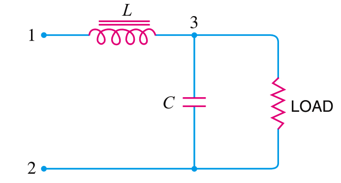
The below Fig. shows a typical choke input filter circuit.  It consists of a Choke L connected in series with the rectifier output and a filter capacitor C across the load. Only a single filter section is shown, but several identical sections are often used to reduce the pulsations as effectively as possible.
Choke Input Filter Operation

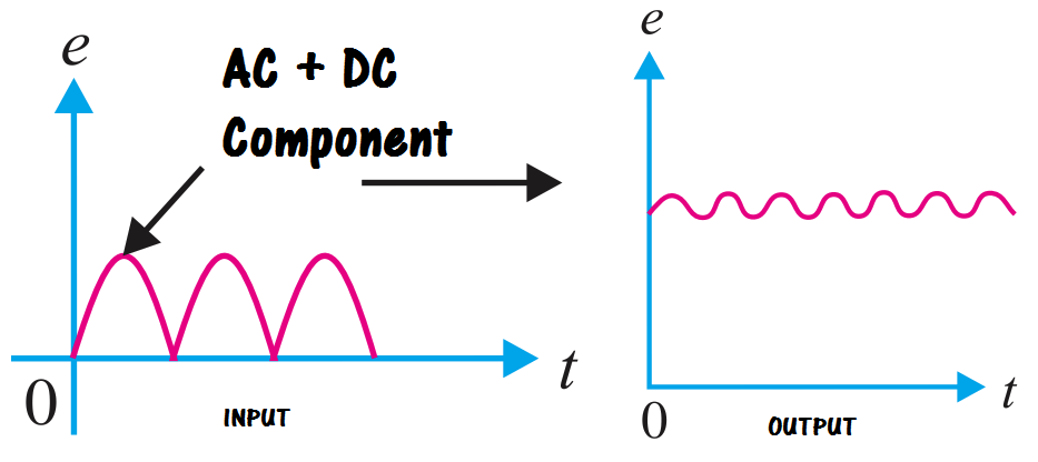
The pulsating output of the rectifier is applied across terminals 1 and 2 of the filter circuit.  As discussed before, the pulsating output of rectifier contains a.c. and d.c. components.  The choke offers high opposition to the passage of a.c. component but negligible opposition to the d.c. component.  The result is that most of the a.c. component appears across the choke while whole of d.c. component passes through the choke on its way to load.  This results in the reduced pulsations at terminal 3.
inductor-filter-output

inductor-principle

Don't Miss Our Updates
Be the first to get exclusive content straight to your email.
We promise not to spam you. You can unsubscribe at any time.
Invalid email address
You've successfully subscribed !

Continue Reading

Transistor Collector Characteristic Curves
What is Kirchhoff’s Current Law
PMMC Temperature Compensation
Freewheeling Diode Working Principle
Photodiode as Variable Resistance Device
Basics of Transistors
Share This Article
Facebook Whatsapp Whatsapp LinkedIn Copy Link
Share
Leave a Comment

Leave a Reply Cancel reply

Your email address will not be published. Required fields are marked *

Stay Connected

128.3kFollowersLike
69.1kFollowersFollow
210kSubscribersSubscribe
38kFollowersFollow

Categories

Explore More

Insulators, Conductors and Semiconductors
Zener Diode Breakdown Characteristics
Transistor as Amplifier
Positive & Negative Diode Clippers
Capacitor Filter Working Principle
Peak Inverse Voltage of Center Tap Rectifier
Transistor Collector Feedback Bias
Resistors Principle & Applications

Keep Learning

MOSFET VI Characteristics

Power MOSFET

phototransistor-circuit

Phototransistor Circuit Example

kirchhoffs-voltage-law

What is Kirchhoff’s Voltage Law

Testing a defective transistor

Testing a Transistor with a Digital Multimeter

full-wave-bridge-rectifier-with-voltage-regulator

Basics of Voltage Regulators

What is a Memristor

What is a Memristor? Principle, Advantages, Applications

Ideal Diode Characteristics

Ideal Diode Characteristics

schottky diode working principle

Schottky Diode Working Principle

Learn More

Solar-Based Engineering Projects

Top 100 Solar-Based Engineering Projects

Demystifying Reynolds Number

Why Viscosity is Not Included in the Orifice Equation?

Industrial Internet of Things Projects

Top 100 Industrial Internet of Things Projects (IIoT)

Level Instruments

Level Instruments General Specifications

Moving Magnet type Velocity Transducer

Moving Magnet Type Velocity Transducer

What is IO-Link in Smart Manufacturing

What is IO-Link in Smart Manufacturing?

Digital Electronics Multiple Choice Questions

Transistor Transistor Logic (TTL) Objective Questions

Free chlorine Analyzer Principle

Free chlorine Analyzer Principle

Menu

  • About
  • Privacy Policy
  • Copyright

Quick Links

  • Learn PLC
  • Helping Hand
  • Part Time Job

YouTube Subscribe

Follow US
All rights reserved. Reproduction in whole or in part without written permission is prohibited.
Welcome Back!

Sign in to your account

Username or Email Address
Password

Lost your password?