Inst ToolsInst ToolsInst Tools
  • Courses
  • Automation
    • PLC
    • Control System
    • Safety System
    • Communication
    • Fire & Gas System
  • Instrumentation
    • Design
    • Pressure
    • Temperature
    • Flow
    • Level
    • Vibration
    • Analyzer
    • Control Valve
    • Switch
    • Calibration
    • Erection & Commissioning
  • Interview
    • Instrumentation
    • Electrical
    • Electronics
    • Practical
  • Q&A
    • Instrumentation
    • Control System
    • Electrical
    • Electronics
    • Analog Electronics
    • Digital Electronics
    • Power Electronics
    • Microprocessor
  • Request
Search
  • Books
  • Software
  • Projects
  • Process
  • Tools
  • Basics
  • Formula
  • Power Plant
  • Root Cause Analysis
  • Electrical Basics
  • Animation
  • Standards
  • 4-20 mA Course
  • Siemens PLC Course
Reading: Instrumentation Diagrams Multiple Choice Questions
Share
Font ResizerAa
Inst ToolsInst Tools
Font ResizerAa
  • Courses
  • Design
  • PLC
  • Interview
  • Control System
Search
  • Courses
  • Automation
    • PLC
    • Control System
    • Safety System
    • Communication
    • Fire & Gas System
  • Instrumentation
    • Design
    • Pressure
    • Temperature
    • Flow
    • Level
    • Vibration
    • Analyzer
    • Control Valve
    • Switch
    • Calibration
    • Erection & Commissioning
  • Interview
    • Instrumentation
    • Electrical
    • Electronics
    • Practical
  • Q&A
    • Instrumentation
    • Control System
    • Electrical
    • Electronics
    • Analog Electronics
    • Digital Electronics
    • Power Electronics
    • Microprocessor
  • Request
Follow US
All rights reserved. Reproduction in whole or in part without written permission is prohibited.
Inst Tools > Blog > Instrumentation MCQ > Instrumentation Diagrams Multiple Choice Questions

Instrumentation Diagrams Multiple Choice Questions

Last updated: June 21, 2025 10:09 am
Editorial Staff
Instrumentation MCQ Multiple Choice Questions
6 Comments
Share
4 Min Read
SHARE

Instrumentation Diagrams Multiple Choice Questions

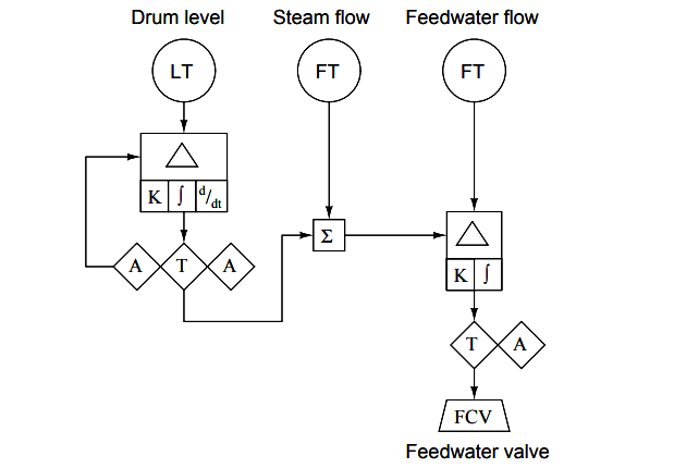
Question 1

Identify what type of diagram this is:

Instrumentation Diagrams

(A) Wiring diagram
(B) Isometric drawing
(C) SAMA diagram
(D) P&ID
(E) Loop diagram

Answer : C

Question 2

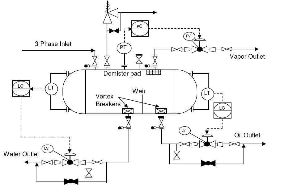
Identify what type of diagram this is:

Piping and Instrumentation Diagram

(A) Wiring diagram
(B) Isometric drawing
(C) Loop diagram
(D) P&ID
(E) SAMA diagram

Answer : D

Question 3

According to this diagram, the controller is , and it is located :

Instrumentation P&ID

(A) Pneumatic, in the field (process) area
(B) Pneumatic, on the front of a secondary control panel
(C) Pneumatic, on the front of the main control panel
(D) Electronic, behind the main control panel
(E) Electronic, on the front of the main control panel

Answer : E

Question 4

Identify the following instrumentation (P&ID and loop diagram) line types, from left to right:

Loop Diagram Lines

(A) pneumatic, electric, capillary, hydraulic
(B) electric, pneumatic, digital network, filled system
(C) pneumatic, electric, hydraulic, mechanical link
(D) electric (on/off), electric (analog), pneumatic, digital network
(E) pneumatic, mechanical link, hydraulic, capillary

Answer : A

Question 5

P&ID stands for ?

(A) Process & Information diagram
(B) Process & Instrumentation diagram
(C) Piping & Information drawings
(D) Piping & Instrumentation diagram

Answer : D

Question 6

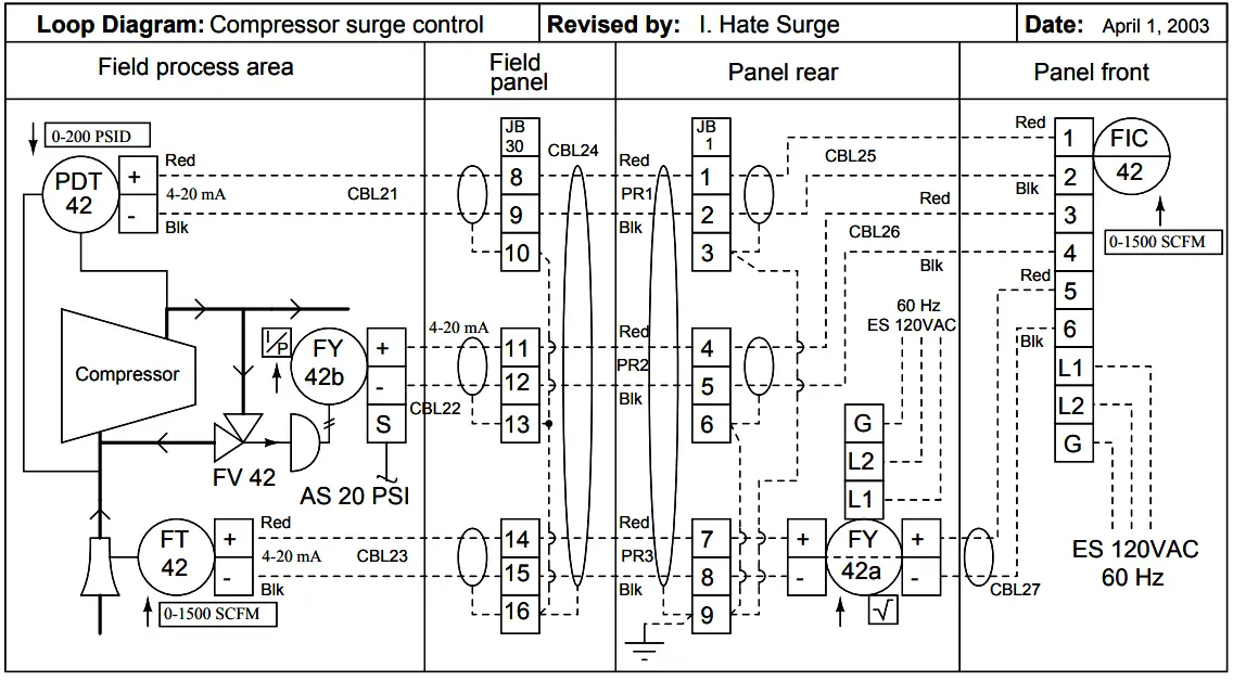
If the gas flow through FT-42 is 1200 SCFM, how much electric current is going through cable 23 and through cable 27 ?

Instrumentation loop Diagram

(A) ICBL23 = 14.2 mA , ICBL27 = 14.2 mA
(B) ICBL23 = 16.8 mA , ICBL27 = 16.8 mA
(C) ICBL23 = 16.8 mA , ICBL27 = 18.3 mA
(D) ICBL23 = 16.8 mA , ICBL27 = 14.2 mA
(E) ICBL23 = 14.2 mA , ICBL27 = 16.8 mA

Answer : E

Question 7

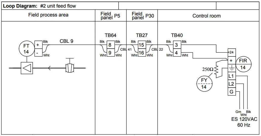
Calculate the voltage between terminals 15 and 16 of TB27 when the measured flow rate is 106 GPM.
Assume a loop power supply voltage of exactly 24.00 volts, and negligible wire resistance:

Instrumentation Plant Diagrams

(A) 26.70 volts
(B) 22.28 volts
(C) 21.30 volts
(D) 24.00 volts
(E) 2.696 volts

Answer : C

Question 8

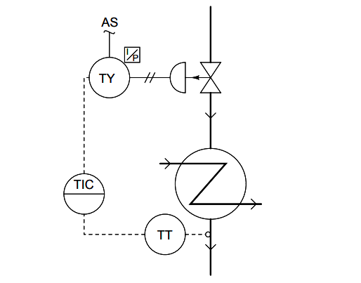
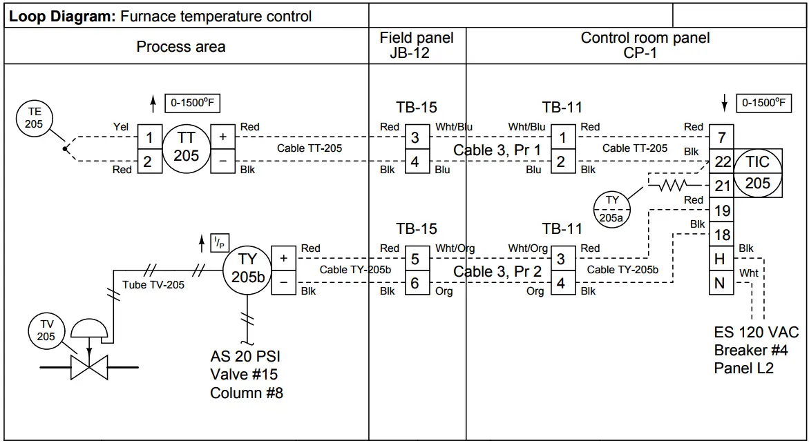
If the thermocouple fails open, what will happen?

Instrumentation Plant Loop Diagrams

(A) Valve TV-205 will hold position, stabilizing the process
(B) Valve TV-205 will close shut, making the process cool down
(C) Valve TV-205 will close shut, making the process warm up
(D) Valve TV-205 will open wide, making the process cool down
(E) Valve TV-205 will open wide, making the process warm up

Answer : B

Question 9

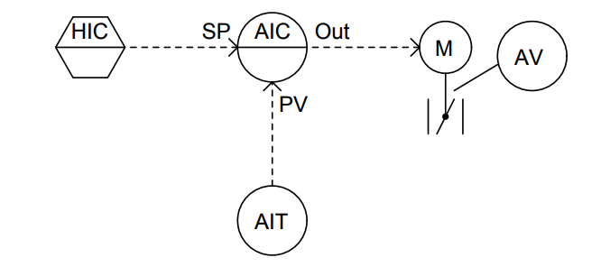
What kind of device provides the setpoint for the analytical indicating controller in this diagram?

P&ID

(A) A Workstation
(B) A mathematical relay
(C) Another panel-mounted controller
(D) A programmable logic controller (PLC)
(E) A pneumatic hand station

Answer : A

Question 10

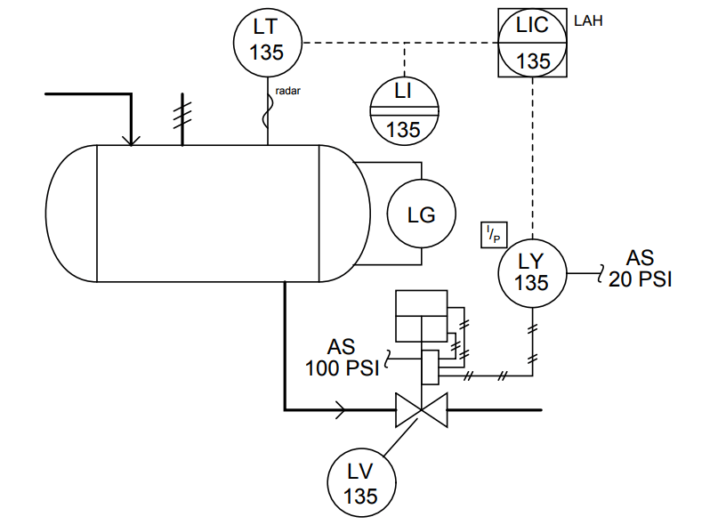
What sort of alarm function is provided by the controller in this diagram?

P&ID Drawing

(A) Low-flow alarm
(B) High-temperature alarm
(C) Low-level alarm
(D) High-flow alarm
(E) High-level alarm

Answer : E

Credits : by Tony R. Kuphaldt
Don't Miss Our Updates
Be the first to get exclusive content straight to your email.
We promise not to spam you. You can unsubscribe at any time.
Invalid email address
You've successfully subscribed !

Continue Reading

Electrical and Instrumentation Test
Digital Circuits Questions & Answers
DC Circuits Multiple Choice Questions
Analog Modulators Objective Questions
Electrical Measurements and Instrumentation Objective Questions & Answers
Components of Mass Spectrometer Questions & Answers
Share This Article
Facebook Whatsapp Whatsapp LinkedIn Copy Link
Share
6 Comments
  • John Patterson says:
    January 10, 2019 at 3:44 pm

    Question 6
    You should have someone check the answer given.

    Question 7
    You are missing at least one piece of information to be able to arrive at an answer.

    Reply
  • Ankur says:
    January 10, 2020 at 7:21 pm

    I agree with john question 6 answer is not correct , information is also not complete for question 6 & 7

    Reply
  • Ed G says:
    January 30, 2020 at 11:57 am

    Question 6:
    I23 = 80%.16+4 = 16.8mA
    I27 = Sqrt(80%).16+ 4 = 18.3 mA

    So C is the correct answer not E ? Am I right ?

    Reply
    • jason dinh says:
      October 7, 2022 at 8:06 pm

      Yes, I agree!

      Reply
  • Ed G says:
    January 30, 2020 at 12:05 pm

    Question 7: I think You should give the transmitter range (0 to 250) GPM

    Reply
  • Ashwin Ganapathy says:
    January 10, 2024 at 10:40 pm

    Can anyone please explain how to do the 8th and 11th questions?

    In the 8th question, how are we determining whether the process is cooling down or warming up?

    In the 11th question, I am confused how the valve positioner works.

    Reply

Leave a Reply Cancel reply

Your email address will not be published. Required fields are marked *

Stay Connected

128.3kFollowersLike
69.1kFollowersFollow
210kSubscribersSubscribe
38kFollowersFollow

Categories

Explore More

Actuators Questions and Answers
Measurement and Instrumentation Objective Questions – Part 2
Encoders and Decoders Objective Questions
Analog to Digital Converters Objective Questions
Wet Contacts and Dry Contacts in PLC Systems
pH Meters Questions & Answers
Closed-Loop Frequency Response
Pressure and Instrumentation MCQ – Questions & Answers

Keep Learning

Time Response Analysis

Standard Test Signals Objective Questions

Electron Spin Resonance Questions & Answers

Instrumentation of ESR Spectrometer

Flow Measurement Quiz

Flow and Level Measurement Quiz

Control Systems Stability and Algebraic Criteria

Routh-Hurwitz Stability Criterion

Digital Control Systems

Difference Equations

Time Response Analysis

Time Response of Second Order Systems – I

Stepper Motor Parts

Stepper Motor MCQ

Pressure Measurement Objective Questions

Pressure Measurement Objective Questions

Learn More

Analog Electronics Objective Questions

Analog Electronics Objective Questions – Set 9

PLC Pump Control

PLC Pump Control: 10 seconds ON & 20 seconds OFF

Motor Protection Relay

Motor Protection Circuits

PLC Code to Start & Stop Motor and Pump as per Logic

PLC Code to Start & Stop Motor and Pump as per Logic

Industrial Automation Acronyms

111 Industrial Automation Acronyms Questions and Answers

Process Control Instrumentation Objective Questions

Process Control & Instrumentation Objective Questions – Set 6

How PLC controls a ON-OFF Valve

PLC Valve Control Ladder Logic Programming

Valves MCQ

Valves MCQ

Menu

  • About
  • Privacy Policy
  • Copyright

Quick Links

  • Learn PLC
  • Helping Hand
  • Part Time Job

YouTube Subscribe

Follow US
All rights reserved. Reproduction in whole or in part without written permission is prohibited.
Welcome Back!

Sign in to your account

Username or Email Address
Password

Lost your password?