Inst ToolsInst ToolsInst Tools
  • Courses
  • Automation
    • PLC
    • Control System
    • Safety System
    • Communication
    • Fire & Gas System
  • Instrumentation
    • Design
    • Pressure
    • Temperature
    • Flow
    • Level
    • Vibration
    • Analyzer
    • Control Valve
    • Switch
    • Calibration
    • Erection & Commissioning
  • Interview
    • Instrumentation
    • Electrical
    • Electronics
    • Practical
  • Q&A
    • Instrumentation
    • Control System
    • Electrical
    • Electronics
    • Analog Electronics
    • Digital Electronics
    • Power Electronics
    • Microprocessor
  • Request
Search
  • Books
  • Software
  • Projects
  • Process
  • Tools
  • Basics
  • Formula
  • Power Plant
  • Root Cause Analysis
  • Electrical Basics
  • Animation
  • Standards
  • 4-20 mA Course
  • Siemens PLC Course
Reading: Diodes Voltage Tripler
Share
Font ResizerAa
Inst ToolsInst Tools
Font ResizerAa
  • Courses
  • Design
  • PLC
  • Interview
  • Control System
Search
  • Courses
  • Automation
    • PLC
    • Control System
    • Safety System
    • Communication
    • Fire & Gas System
  • Instrumentation
    • Design
    • Pressure
    • Temperature
    • Flow
    • Level
    • Vibration
    • Analyzer
    • Control Valve
    • Switch
    • Calibration
    • Erection & Commissioning
  • Interview
    • Instrumentation
    • Electrical
    • Electronics
    • Practical
  • Q&A
    • Instrumentation
    • Control System
    • Electrical
    • Electronics
    • Analog Electronics
    • Digital Electronics
    • Power Electronics
    • Microprocessor
  • Request
Follow US
All rights reserved. Reproduction in whole or in part without written permission is prohibited.
Inst Tools > Blog > Electronic Devices & Circuits > Diodes Voltage Tripler

Diodes Voltage Tripler

Last updated: October 5, 2016 12:51 pm
Editorial Staff
Electronic Devices & Circuits
No Comments
Share
1 Min Read
SHARE

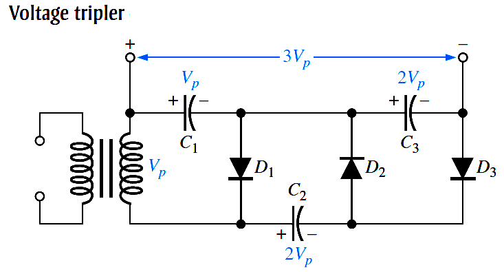
The addition of another diode-capacitor section to the half-wave voltage doubler creates a voltage tripler, as shown in Below Figure.

The operation is as follows: On the positive half-cycle of the secondary voltage, C1 charges to Vp through D1. During the negative halfcycle, C2 charges to 2Vp through D2, as described for the doubler. During the next positive half-cycle, C3 charges to 2Vp through D3. The tripler output is taken across C1 and C3, as shown in the figure.

Diodes Voltage Tripler

Don't Miss Our Updates
Be the first to get exclusive content straight to your email.
We promise not to spam you. You can unsubscribe at any time.
Invalid email address
You've successfully subscribed !

Continue Reading

Resistors Principle & Applications
Transistor Biasing
Circuit Elements and Types of Circuits
N Type and P Type Semiconductors
Testing a Transistor with a Digital Multimeter
Half Wave Voltage Doubler using Diodes
Share This Article
Facebook Whatsapp Whatsapp LinkedIn Copy Link
Share
Leave a Comment

Leave a Reply Cancel reply

Your email address will not be published. Required fields are marked *

Stay Connected

128.3kFollowersLike
69.1kFollowersFollow
210kSubscribersSubscribe
38kFollowersFollow

Categories

Explore More

Voltage Divider Rule
Amplifiers Questions & Answers
Why Silicon is preferred over Germanium ?
Transistor Base Bias
Comparison of Transistor Configurations
Combining Independent Current Sources in Parallel
Ripple Voltage in Rectifiers
Half Wave Rectifier Principle

Keep Learning

JFET Working Animation

JFET Working Animation

Comparison of Half wave Rectifiers and Full wave Rectifiers

Comparison of Half wave Rectifiers and Full wave Rectifiers

pn-junction-energy-diagrams

Energy Diagrams of PN Junction & Depletion Region

Transistor Emitter Feedback Bias

Transistor Emitter Feedback Bias

Optoisolator Working Principle

Optoisolator Working Principle

Center Tapped Full Wave Rectifier Operation

Center Tapped Full Wave Rectifier Operation

reverse-biased varactor diode

Varactor Diode Operation

Photodiode as Variable Resistance Device

Photodiode as Variable Resistance Device

Learn More

Basics-of-Gas-Chromatograph-Working-Principle

Working Principle of Gas chromatograph

Differences between Watts and Volt Amps

Differences between Watts and Volt Amps

Factory Acceptance Test of PLC Panel

Factory Acceptance Test (FAT) of a PLC Panel

Temperature Gauges and Elements Specifications

Temperature Gauges and Elements : Detailed Specifications

Types of Transfomer Cooling Methods

Digital Electronics Multiple Choice Questions

Asynchronous Down Counter Objective Questions

Simatic Prosave HMI

How to Backup and Restore from Simatic Prosave HMI?

Digital Circuits Questions & Answers

Digital Circuits Questions & Answers

Menu

  • About
  • Privacy Policy
  • Copyright

Quick Links

  • Learn PLC
  • Helping Hand
  • Part Time Job

YouTube Subscribe

Follow US
All rights reserved. Reproduction in whole or in part without written permission is prohibited.
Welcome Back!

Sign in to your account

Username or Email Address
Password

Lost your password?