Temperature Transmitter Foundation Fieldbus
Configure the AI block
A minimum of four parameters are required to configure the AI Block. The parameters are described below with example configurations shown at the end of this section.
CHANNEL : Select the channel that corresponds to the desired sensor measurement. The FF transmitter measures both sensor temperature (channel 1) and terminal temperature (channel 2).
L_TYPE : The L_TYPE parameter defines the relationship of the sensor measurement (sensor temperature) to the desired output temperature of the AI Block. The relationship can be direct or indirect.
Direct : Select direct when the desired output will be the same as the sensor measurement (sensor temperature).
Indirect : Select indirect when the desired output is a calculated measurement based on the sensor measurement (e.g. ohm or mV). The relationship between the sensor measurement and the calculated measurement will be linear.
XD_SCALE and OUT_SCALE : The XD_SCALE and OUT_SCALE each include four parameters: 0%, 100%, engineering units, and precision (decimal point). Set these based on the L_TYPE:
L_TYPE is Direct : When the desired output is the measured variable, set the XD_SCALE to represent the operating range of the process. Set OUT_SCALE to match XD_SCALE.
L_TYPE is Indirect : When an inferred measurement is made based on the sensor measurement, set the XD_SCALE to represent the operating range that the sensor will see in the process. Determine the inferred measurement values that correspond to the XD_SCALE 0 and 100% points and set these for the OUT_SCALE.
NOTE : To avoid configuration errors, only select Engineering Units for XD_SCALE and OUT_SCALE that are supported by the device.
Temperature Transmitter Foundation Fieldbus Configuration Examples
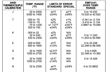
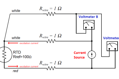
Consider our temperature element is 4-wire, Pt 100, α = 0.385
Every FF transmitter Transducer block have two minimum AI channels.
AI1 = Process Temperature
AI2 = Terminal Temperature
Transducer Block
Through HART FF communicator:
1. Put transducer block into OOS mode.
a. Go to MODE_BLK.TARGET
b. Choose OOS
2. Go to SENSOR_CONNECTION.
a. Choose 4-wire (0x4)
3. Go to SENSOR_TYPE.
a. Choose PT100A385
4. Put the transducer block back into Auto mode.
AI Blocks (Basic Configuration)
AI1 as Process Temperature
1. Put the AI Block into OOS mode.
a. Go to MODE_BLK.TARGET
b. Choose OOS
2. Go to CHANNEL
a. Choose Sensor 1
3. Go to L_TYPE
a. Choose Direct
4. Go to XD_Scale
a. Choose UNITS_INDEX to be °C
5. Go to OUT_SCALE
a. Choose UNITS_INDEX to be °C
b. Set the 0 and 100 scale to be the same as the PRIMARY_VALUE_RANGE
6. Put the AI Block back into Auto mode.
Note : PRIMARY_VALUE_RANGE is the range of your transmitter.
AI2 as Terminal Temperature
1. Put the AI Block into OOS mode.
a. Go to MODE_BLK.TARGET
b. Choose OOS (0x80)
2. Go to CHANNEL
a. Choose Body Temperature
3. Go to L_TYPE
a. Choose Direct
4. Go to XD_Scale
a. Choose UNITS_INDEX to be °C
5. Go to OUT_SCALE
a. Choose UNITS_INDEX to be °C
b. Set the 0 and 100 scale to be the same as the SECONDARY_VALUE_RANGE
6. Put the AI Block back into Auto mode.
7. Follow Host Procedure Download Schedule into Block.
Sensor Transducer Block
Sensor Calibration, Lower and Upper Trim Methods
In order to calibrate the transmitter, run the Lower and Upper Trim Methods. If your system does not support methods, manually configure the Transducer Block parameters listed below.
1. Set MODE_BLK.TARGET to OOS
2. Set SENSOR_CAL_METHOD to User Trim
3. Set CAL_UNIT to supported engineering units in the Transducer Block
4. Apply temperature that corresponds to the lower calibration point and allow the temperature to stabilize. The temperature must be between the range limits defined in PRIMRY_VALUE_RANGE.
5. Set values of CAL_POINT_LO to correspond to the temperature applied by the sensor.
6. Apply temperature, temperature corresponding to the upper calibration
7. Allow temperature to stabilize.
8. Set CAL_POINT_HI
9. Set SENSOR_CAL_DATE to the current date.
10. Set SENSOR_CAL_WHO to the person responsible for the calibration.
11. Set SENSOR _CAL_LOC to the calibration location.
12. Set MODE_BLK.TARGET to AUTO
Note :
- CAL_POINT_HI must be within PRIMARY_VALUE_RANGE and greater than CAL_POINT_LO + AL_MIN_SPAN
- If trim fails the transmitter will automatically revert to factory trim.
- Excessive correction or sensor failure could cause device status to read calibration error. To clear this, trim the transmitter
Recall Factory Trim
To recall a factory trim on the transmitter, run the Recall Factory Trim. If your system does not support methods, manually configure the Transducer Block parameters listed below.
1. Set MODE_BLK.TARGET to OOS
2. Set SENSOR_CAL_METHOD to Factory Trim.
3. Set SET_FACTORY_TRIM to Recall.
4. Set SENSOR_CAL_DATE to the current date.
5. Set SENSOR_CAL_WHO to the person responsible for the calibration.
6. Set SENSOR _CAL_LOC to the calibration location.
7. Set MODE_BLK.TARGET to AUTO.
NOTE : When sensor type is changed, the transmitter reverts to the factory trim. Changing sensor type causes you to loose any trim performed on the transmitter.
Simulation
Simulate replaces the channel value coming from the Sensor Transducer Block. For testing purposes, it is possible to manually drive the output of the Analog Input Block to a desired value. There are two ways to do this.
Manual Mode : To change only the OUT_VALUE and not the OUT_STATUS of the AI Block, place the TARGET MODE of the block to MANUAL. Then, change the OUT_VALUE to the desired value.
How to Simulate FF Device ?
1. If the SIMULATE switch is in the OFF position, move it to the ON position. If the SIMULATE jumper is already in the ON position, you must move it to off and place it back in the ON position.
2. To change both the OUT_VALUE and OUT_STATUS of the AI Block, set the TARGET MODE to AUTO.
3. Set SIMULATE_ENABLE_DISABLE to Active.
4. Enter the desired SIMULATE_VALUE to change the OUT_VALUE and SIMULATE_STATUS_QUALITY to change the OUT_STATUS. If errors occur when performing the above steps, be sure that the SIMULATE jumper has been reset after powering up the device.
NOTE : As a safety measure, the switch must be reset every time power is interrupted to the device in order to enable SIMULATE. This prevents a device that is tested on the bench from getting installed in the process with SIMULATE still active.
Reference : Rosemount Temperature Manual


nice explanation , Mr can you explain how to calibration FF Pressure Transmitter and FF Control Valve
Thanks in advanced…
Very good explanation.Good job..Very useful for US.
Sir please give me one solution how to do FF level transmitter calculation
how to simulate FF type temperature transmitter using hart 475 communicator or Trex communicator. Thanks in advance