Inst ToolsInst ToolsInst Tools
  • Courses
  • Automation
    • PLC
    • Control System
    • Safety System
    • Communication
    • Fire & Gas System
  • Instrumentation
    • Design
    • Pressure
    • Temperature
    • Flow
    • Level
    • Vibration
    • Analyzer
    • Control Valve
    • Switch
    • Calibration
    • Erection & Commissioning
  • Interview
    • Instrumentation
    • Electrical
    • Electronics
    • Practical
  • Q&A
    • Instrumentation
    • Control System
    • Electrical
    • Electronics
    • Analog Electronics
    • Digital Electronics
    • Power Electronics
    • Microprocessor
Search
  • Books
  • Software
  • Projects
  • Process
  • Tools
  • Basics
  • Formula
  • Power Plant
  • Root Cause Analysis
  • Electrical Basics
  • Animation
  • Standards
  • 4-20 mA Course
  • Siemens PLC Course
Reading: Dependent Voltage Source
Share
Notification Show More
Font ResizerAa
Inst ToolsInst Tools
Font ResizerAa
  • Courses
  • Design
  • PLC
  • Interview
  • Control System
Search
  • Courses
  • Automation
    • PLC
    • Control System
    • Safety System
    • Communication
    • Fire & Gas System
  • Instrumentation
    • Design
    • Pressure
    • Temperature
    • Flow
    • Level
    • Vibration
    • Analyzer
    • Control Valve
    • Switch
    • Calibration
    • Erection & Commissioning
  • Interview
    • Instrumentation
    • Electrical
    • Electronics
    • Practical
  • Q&A
    • Instrumentation
    • Control System
    • Electrical
    • Electronics
    • Analog Electronics
    • Digital Electronics
    • Power Electronics
    • Microprocessor
Follow US
All rights reserved. Reproduction in whole or in part without written permission is prohibited.
Inst Tools > Blog > Electronic Devices & Circuits > Dependent Voltage Source

Dependent Voltage Source

Last updated: October 6, 2016 6:33 am
Editorial Staff
Electronic Devices & Circuits
No Comments
Share
2 Min Read
SHARE

Dependent Sources

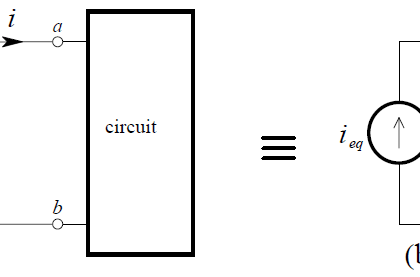
An ideal source, either voltage or current, whose value depends upon some parameter (usually a voltage or current) in the circuit to which the source belongs is known as a dependent or controlled source.

The Dependent Voltage Source

A dependent voltage source establishes a voltage across its terminals, independent of the current through it, which is determined by the voltage or current at some other location in the electrical system. There are two types of dependent voltage source – the voltage-controlled voltage source (VCVS) and the current-controlled voltage source (CCVS).

Dependent Voltage Source

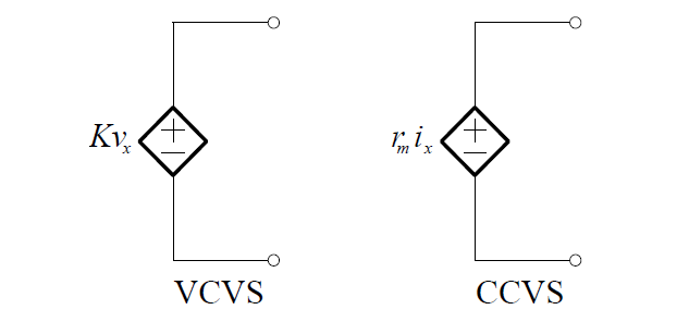
Note that the dependent source is represented by a diamond-shaped symbol so as not to confuse it with an independent source.

These  sources  are  mathematical  models  that  are  useful  in  modelling  real circuits and systems, e.g. they are used in modelling operational amplifiers.

Example:

Consider the circuit shown below. This circuit contains a dependent source whose value in this case depends on the voltage across the 4 Ω resistor – it is a VCVS.

dependent-voltage-source-circuit-example

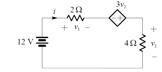
To analyse the circuit, we apply KVL and obtain:

v1 – 3v2  + v2  = 12

or:

v1 – 2v2  = 12

By Ohm’s Law:

v1  = 2i

and

v2  = 4i

Therefore:

2i – 2(4i ) = 12

2i – 8i = 12

– 6i = 12

i = -2 A

Hence:

v2  = 4i = -8 V

and the value of the dependent voltage source is:

3v2  = -24 V


Don't Miss Our Updates
Be the first to get exclusive content straight to your email.
We promise not to spam you. You can unsubscribe at any time.
Invalid email address
You've successfully subscribed !

Continue Reading

Combining Independent Current Sources in Parallel
Forward Bias & Reverse Bias Diode Working Animation
Diodes Voltage Quadrupler
Current Divider Rule
Phototransistor Circuit Example
What is a Memristor? Principle, Advantages, Applications
Share This Article
Facebook Whatsapp Whatsapp LinkedIn Copy Link
Share
Leave a Comment

Leave a Reply Cancel reply

Your email address will not be published. Required fields are marked *

Stay Connected

128.3kFollowersLike
69.1kFollowersFollow
210kSubscribersSubscribe
38kFollowersFollow

Categories

Explore More

Laser Diode Working Principle
Capacitively Coupled Multistage Transistor Amplifier
Capacitor Filter Working Principle
Forward Bias & Reverse Bias of a Diode
Applications of Photo diodes
Transistor Emitter Feedback Bias
Transistor Emitter Bias
What is Kirchhoff’s Current Law

Keep Learning

Permanent magnet moving coil instruments (PMMC)

Permanent Magnet Moving Coil Instruments (PMMC)

Comparison of CB, CE & CC Amplifiers

Comparison of Transistor Configurations

Current Limiting Resistor

Resistors Principle & Applications

pn-junction-energy-diagrams

Energy Diagrams of PN Junction & Depletion Region

Diode-positive-limiter

Positive & Negative Diode Clippers

Cathode Ray Tube Deflection System

Cathode Ray Tube Deflection System

Power MOSFET Safe Operating Area

Power MOSFET Safe Operating Area

Choke Input Filter Operation

Choke Input Filter Operation

Learn More

PID Control Theory

Overview of PID Control terms

Sequential Timer Control of Lamps

Schneider PLC Example: Control Lamps Sequences

Best Engineering Mobile Apps

Best Engineering Mobile Apps on Google Play & App Store

Wrongly terminated Thermocouple (TC) wires

Too Low-Temperature Readings after a Failed Thermocouple Change

reactor vessel

Practical Process Control System Questions & Answers – 5

Sand Probe Functional Testing

Sand Probe Functional Testing

Inspection and Testing of Fiber Optic Cable

Inspection and Testing of Fiber Optic Cable

Beam Balance Systems Objective Questions

Beam Balance Systems Objective Questions

Menu

  • About
  • Privacy Policy
  • Copyright

Quick Links

  • Learn PLC
  • Helping Hand
  • Part Time Job

YouTube Subscribe

Follow US
All rights reserved. Reproduction in whole or in part without written permission is prohibited.
Welcome Back!

Sign in to your account

Username or Email Address
Password

Lost your password?