By using this site, you agree to the Privacy Policy and Terms of Use.
Accept
Inst ToolsInst ToolsInst Tools
  • Ask
  • Courses
  • Videos
  • Q & A
    • Interview
      • Instrumentation
      • Electronics
      • Electrical
      • Practical Questions
    • MCQ
      • Instrumentation MCQ
      • Electrical MCQ
      • Electronics MCQ
      • Control Systems MCQ
      • Analog Electronics MCQ
      • Digital Electronics MCQ
      • Power Electronics MCQ
      • Microprocessor MCQ
      • Multiple Choice Questions
  • EE
    • Electronics
      • Electronics Q & A
      • Electronic Basics
      • Electronic Devices & Circuits
      • Electronics Animation
      • Digital Electronics
    • Electrical
      • Electrical Basics
      • Electrical Q & A
      • Power Electronics
      • Electrical Machines
      • Electrical Animation
      • Power Systems
      • Switchgear & Protection
      • Transmission & Distribution
  • Measure
    • Control Valves
    • Calibration
    • Temperature
    • Pressure
    • Flow
    • Level
    • Analyzers
    • Switches
    • Vibration
    • Solenoid Valve
  • Control
    • PLC Tutorials
    • Control Systems
    • Safety Instrumented System (SIS)
    • Communication
    • Fire & Gas System
  • More
    • Design
    • Tools
    • Animation
    • Basics
    • Formulas
    • Standards
    • TextBooks
    • Common
    • Software
    • Excel Tools
    • Erection & Commissioning
    • Process Fundamentals
    • Videos
    • Books
Search
All rights reserved. Reproduction in whole or in part without written permission is prohibited.
Reading: 3 Valve Manifold Operation
Share
Notification Show More
Font ResizerAa
Inst ToolsInst Tools
Font ResizerAa
  • Ask
  • Courses
  • Videos
  • Q & A
  • EE
  • Measure
  • Control
  • More
Search
  • Ask
  • Courses
  • Videos
  • Q & A
    • Interview
    • MCQ
  • EE
    • Electronics
    • Electrical
  • Measure
    • Control Valves
    • Calibration
    • Temperature
    • Pressure
    • Flow
    • Level
    • Analyzers
    • Switches
    • Vibration
    • Solenoid Valve
  • Control
    • PLC Tutorials
    • Control Systems
    • Safety Instrumented System (SIS)
    • Communication
    • Fire & Gas System
  • More
    • Design
    • Tools
    • Animation
    • Basics
    • Formulas
    • Standards
    • TextBooks
    • Common
    • Software
    • Excel Tools
    • Erection & Commissioning
    • Process Fundamentals
    • Videos
    • Books
Follow US
All rights reserved. Reproduction in whole or in part without written permission is prohibited.
Inst Tools > Blog > Common > 3 Valve Manifold Operation
CommonPressure Measurement

3 Valve Manifold Operation

Last updated: June 12, 2018 4:23 pm
Editorial Staff
Share
2 Min Read
SHARE

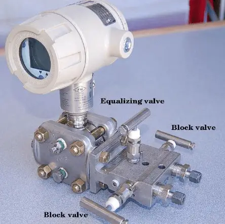
A three-valve manifold is a device that is used to ensure that the capsule will not be over-ranged. It also allows isolation of the transmitter from the process loop. It consists of two block valves – high pressure and low pressure block valve – and an equalizing valve. Two block valves provide instrument isolation, and one equalize valve is positioned between the high and low transmitter process connections to provide equal pressures on both sides.

The below figure shows a three valve manifold arrangement.

Three Valve Manifold

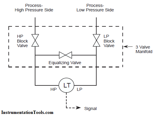
During normal operation, the equalizing valve is closed and the two block valves are open. When the transmitter is put into or removed from service, the valves must be operated in such a manner that very high pressure is never applied to only one side of the DP capsule.

DP Transmitter with Manifold

Operational Sequences of Three-Valve Manifold Valving Transmitter into Service:

To valve a DP transmitter into service an operator would perform the following steps:

1.Check all valves are closed.

2.Open the equalizing valve – this ensures that the same pressure will be applied to both sides of the transmitter, i.e., zero differential pressure.

3.Open the High Pressure block valve slowly, check for leakage from both the high pressure and low-pressure side of the transmitter.

4.Close the equalizing valve – this locks the pressure on both sides of the transmitter.

5.Open the low-pressure block valve to apply process pressure to the low-pressure side of the transmitter and establish the working differential pressure.

6.The transmitter is now in service.

Note it may be necessary to bleed any trapped air from the capsule housing.

Removing Transmitter from Service:

Reversal of the above steps allows the DP transmitter to be removed from service:

1.Close the low-pressure block valve.

2.Open the equalizing valve.

3.Close the high-pressure block valve.

The transmitter is now out of service.

Note the transmitter capsule housing still contains process pressure; this will require bleeding.

Also Read: Basics of Thermocouples & RTD

Don't Miss Our Updates
Be the first to get exclusive content straight to your email.
We promise not to spam you. You can unsubscribe at any time.
Invalid email address
You've successfully subscribed !
Cold Email Deliverability – Latest Comprehensive Guide
Things You Should Know About Swiss Screw Machining
The Importance of Supply Chain Collaboration
PM of Instrument Air Compressor in Oil & Gas Plants
Bellows Pressure Sensors Working Principle Animation
Share This Article
Facebook Whatsapp Whatsapp LinkedIn Copy Link
Share
1 Comment
  • Mohamed Irshad says:
    October 25, 2016 at 9:58 am

    Now i am cleared about transmitter manifold. Insert a like button if you could..!!!!

    Reply

Leave a Reply Cancel reply

Your email address will not be published. Required fields are marked *

Stay Connected

128.3kFollowersLike
69.1kFollowersFollow
206kSubscribersSubscribe
38kFollowersFollow

Latest

Top Non-PLC Certification Courses for Automation Professionals
Common
Things You Need to Know About DeviceNet
Communication
Why is IEC 60269 Important
Why is IEC 60269 Important? – Electrical Applications
Standards
NAMUR OPEN ARCHITECTURE
What is NAMUR OPEN ARCHITECTURE?
Control Systems

More Articles

what-is-gas-metering-system

What is Gas Metering System?

Basic Pneumatic System

Introduction to Fluid Power and Pneumatics

PID Tuner

Free PID Controller Gains Tuning Tool

Electrical Symbols

Electrical Symbols

Fixed PLC

#19 PLC Best Practices – Monitor PLC Memory Usage

Sinking and Sourcing Devices Operation

PLC Sinking and Sourcing Explanation

Omron PLC real-time clock street lighting program

Automatic Highway Lights Program using RTC in Omron PLC

System architecture

Types of System Architecture used in Industrial Automation

//

Inst Tools

Sign Up for Our Newsletter

Subscribe to our newsletter to get our newest articles instantly!

[mc4wp_form id=”847″]

Follow US
All rights reserved. Reproduction in whole or in part without written permission is prohibited.
Welcome Back!

Sign in to your account

Username or Email Address
Password

Lost your password?