Inst ToolsInst ToolsInst Tools
  • Courses
  • Automation
    • PLC
    • Control System
    • Safety System
    • Communication
    • Fire & Gas System
  • Instrumentation
    • Design
    • Pressure
    • Temperature
    • Flow
    • Level
    • Vibration
    • Analyzer
    • Control Valve
    • Switch
    • Calibration
    • Erection & Commissioning
  • Interview
    • Instrumentation
    • Electrical
    • Electronics
    • Practical
  • Q&A
    • Instrumentation
    • Control System
    • Electrical
    • Electronics
    • Analog Electronics
    • Digital Electronics
    • Power Electronics
    • Microprocessor
  • Request
Search
  • Books
  • Software
  • Projects
  • Process
  • Tools
  • Basics
  • Formula
  • Power Plant
  • Root Cause Analysis
  • Electrical Basics
  • Animation
  • Standards
  • 4-20 mA Course
  • Siemens PLC Course
Reading: Cascade Control Principle
Share
Font ResizerAa
Inst ToolsInst Tools
Font ResizerAa
  • Courses
  • Design
  • PLC
  • Interview
  • Control System
Search
  • Courses
  • Automation
    • PLC
    • Control System
    • Safety System
    • Communication
    • Fire & Gas System
  • Instrumentation
    • Design
    • Pressure
    • Temperature
    • Flow
    • Level
    • Vibration
    • Analyzer
    • Control Valve
    • Switch
    • Calibration
    • Erection & Commissioning
  • Interview
    • Instrumentation
    • Electrical
    • Electronics
    • Practical
  • Q&A
    • Instrumentation
    • Control System
    • Electrical
    • Electronics
    • Analog Electronics
    • Digital Electronics
    • Power Electronics
    • Microprocessor
  • Request
Follow US
All rights reserved. Reproduction in whole or in part without written permission is prohibited.
Inst Tools > Blog > Control Systems > Cascade Control Principle

Cascade Control Principle

Last updated: December 6, 2019 8:14 pm
Editorial Staff
Control Systems
3 Comments
Share
5 Min Read
SHARE

What is Cascade Control?

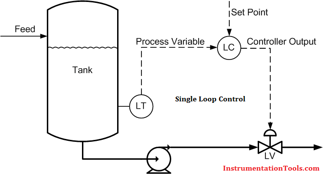
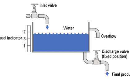
In single-loop control, the controller’s set point is set by an operator, and its output drives a final control element. For example: a level controller driving a control valve to keep the level at its set point.

Single Loop Control

In a cascade control arrangement, there are two (or more) controllers of which one controller’s output drives the set point of another controller. For example: a level controller driving the set point of a flow controller to keep the level at its set point. The flow controller, in turn, drives a control valve to match the flow with the set point the level controller is requesting.

Cascade Control

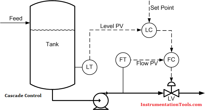
The controller driving the set point (the level controller in the example above) is called the primary, outer, or master controller. The controller receiving the set point (flow controller in the example) is called the secondary, inner or slave controller.

Cascade control can improve control system performance over single-loop control whenever either: (1) Disturbances affect a measurable intermediate or secondary process output that directly affects the primary process output that we wish to control; or (2) the gain of the secondary process, including the actuator, is nonlinear. In the first case, a cascade control system can limit the effect of the disturbances entering the secondary variable on the primary output. In the second case, a cascade control system can limit the effect of actuator or secondary process gain variations on the control system performance. Such gain variations usually arise from changes in operating point due to setpoint changes or sustained disturbances.

When Should Cascade Control be Used?

Cascade control should always be used if you have a process with relatively slow dynamics (like level, temperature, composition, humidity) and a liquid or gas flow, or some other relatively-fast process, has to be manipulated to control the slow process. For example: changing cooling water flow rate to control condenser pressure (vacuum), or changing steam flow rate to control heat exchanger outlet temperature. In both cases, flow control loops should be used as inner loops in cascade arrangements.

Does Cascade Control Have any Disadvantages?

Cascade control has three disadvantages. One, it requires an additional measurement (usually flow rate) to work. Two, there is an additional controller that has to be tuned. And three, the control strategy is more complex – for engineers and operators alike. These disadvantages have to be weighed up against the benefits of the expected improvement in control to decide if cascade control should be implemented.

When Should Cascade Control Not be Used?

Cascade control is beneficial only if the dynamics of the inner loop are fast compared to those of the outer loop. Cascade control should generally not be used if the inner loop is not at least three times faster than the outer loop, because the improved performance may not justify the added complexity.

In addition to the diminished benefits of cascade control when the inner loop is not significantly faster than the outer loop, there is also a risk of interaction between the two loops that could result in instability – especially if the inner loop is tuned very aggressively.

How Should Cascade Controls be Tuned?

A cascade arrangement should be tuned starting with the innermost loop. Once that one is tuned, it is placed in cascade control, or external set point mode, and then the loop driving its set point is tuned. Do not use quarter-amplitude-damping tuning rules (such as the unmodified Ziegler-Nichols and Cohen-Coon rules) to tune control loops in a cascade structure because it can cause instability if the process dynamics of the inner and outer loops are similar.

Don't Miss Our Updates
Be the first to get exclusive content straight to your email.
We promise not to spam you. You can unsubscribe at any time.
Invalid email address
You've successfully subscribed !

Continue Reading

PID Controllers : Parallel, Ideal & Series
Identify Process Variables in P&ID
PID Controller Loop Tuning Questions and Answers – Part 1
Basics of 4-20mA Current Loop
How to Do Loop Checks During Plant Pre-Commissioning
Instrumentation and Electrical Teams Interactions (Detail Design Engineering)
Share This Article
Facebook Whatsapp Whatsapp LinkedIn Copy Link
Share
3 Comments
  • Akshay says:
    November 6, 2017 at 5:07 pm

    For cascade control above example..there are two controller used.So what are the process Variable and control variable for this two controller ?

    Reply
  • Dheeraj says:
    December 29, 2022 at 9:41 am

    Master Controller’s variable will be work as PV and SV. in the above example Level controller will be the master controller.

    Reply
  • Innocent Menuchimso Bob-Weke says:
    January 28, 2024 at 11:59 pm

    Thanks

    Reply

Leave a Reply Cancel reply

Your email address will not be published. Required fields are marked *

Stay Connected

128.3kFollowersLike
69.1kFollowersFollow
210kSubscribersSubscribe
38kFollowersFollow

Categories

Explore More

What is FAT and SAT? Difference between them
Industrial Automation System Architecture Reference Model
20 Most Common Types of Cyber Attacks
DeltaV System Configuration Changes and Download
Switch or Transmitter
What is Data Acquisition? – Elements and Components
Centrifugal Compressor Start Permissive and Interlocks
Example of Feedback System

Keep Learning

Why 24 Volts DC Power Supply

Why 24 Volts DC Power Supply is used? – Industrial Automation Systems

Burner Control Loop Graphics

Burner Safety Logic for Initial Lighting

PLC DIN Rail

What is DIN rail ?

DCS System Layout and its Different Parts

DCS System Layout and its Different Parts

What is Process Control ?

What is Process Control?

Cascade Control System

Cascade Control

Supervisory Control

Supervisory Control

Basics of Anti-Surge Control System

What is Anti Surge System?

Learn More

MEASURING AN NPT CONNECTION

NPT Connection Measurement Size

Self Balancing Bridges Objective Questions

Bridge Circuits Objective Questions

HART Multidrop Network

HART Communication Tutorial Part 2

PLC NOR Logic

Logic Gates in PLC Ladder Logic

PLC Question Bank

PLC Question Bank

Conductivity measurement

Conductivity Measurement

Turbine Flow meter coefficient

Turbine Flow Meter Coefficient and Scaling Factor

Digital Electronics Multiple Choice Questions

Programmable Logic Array Objective Questions

Menu

  • About
  • Privacy Policy
  • Copyright

Quick Links

  • Learn PLC
  • Helping Hand
  • Part Time Job

YouTube Subscribe

Follow US
All rights reserved. Reproduction in whole or in part without written permission is prohibited.
Welcome Back!

Sign in to your account

Username or Email Address
Password

Lost your password?