The Network Gateway is a critically important component in a WirelessHART system. It is the sole channel through which all field device data funnels to the host control system. Physically, a network gateway is nothing more than a box with an antenna on it, and connections within for electrical power and wired networks (e.g. Ethernet, EIA/TIA-485). Shown here is an Emerson model 1420 “Smart Wireless Gateway”:
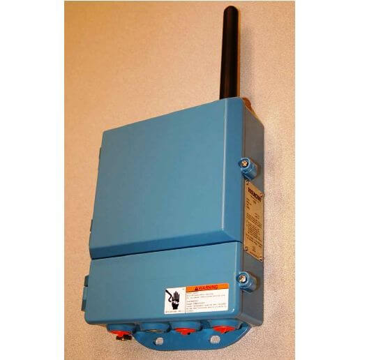
Electrically, these devices are quite complex. They are microprocessor-controlled, and often serve as the physical host for the Network Manager algorithm: orchestrating and tuning the wireless network communications.
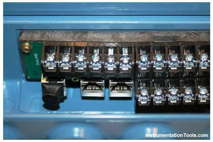
Since WirelessHART is a purely digital communication standard, all data points from the field devices are stored in the gateway in digital form, and must be accessed digitally. In the case of Emerson’s Smart Wireless Gateway, the data may be accessed by any host system via Modbus query commands, communicated either serially (EIA/TIA-485, Modbus RTU format) or encapsulated in Ethernet packets (Modbus TCP). Screw terminal connections exist on the Emerson gateway for an EIA/TIA-485 (RS-485) cable to connect, as well as multiple RJ-45 Ethernet ports for connection to a hub or switch where other Ethernet-based computers and systems may connect as well:
Like so many other industrial Ethernet-ready devices, the Emerson Smart Wireless Gateway has a built-in web server, allowing password-protected access to configuration pages using nothing more than a personal computer with Ethernet connectivity and a web (Internet) browser program. Simply type the IP address of the gateway port into the browser’s URL field, and the personal computer will connect to the gateway.
Individual device data points are custom-mapped by the user to specific Modbus registers inside the gateway’s memory, as shown on this configuration page:
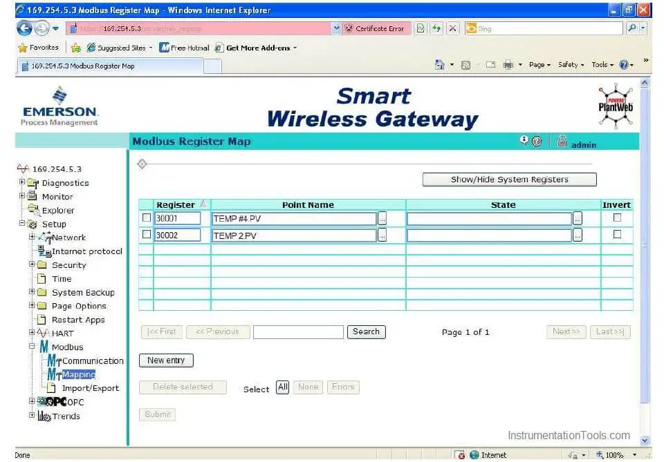
In this screenshot we see the primary variables (PV) of two Rosemount model 648 WirelessHART temperature transmitters mapped to Modbus registers 30001 and 30002. It should be noted that all WirelessHART field instruments are multi-variable devices, and as such are capable of reporting more than one variable to the gateway.
Note : Device variables are addressed at the network gateway level by the device’s HART tag (long tag, not short tag) and internal device variable name. Thus, the primary variable (PV) of temperature transmitter TEMP2 is specified as TEMP2.PV using a period symbol (.) as the delimiting character between the device name and the internal variable name.
If anyone were interested, it would have been possible in this example to assign battery voltage as a secondary variable (SV), tertiary variable (TV), or quaternary variable (QV) inside one or both temperature transmitters, then map those data points to their own Modbus registers in the gateway so that a host system could access and monitor battery voltage for the field instruments. Just as in wired-HART communication, multivariable data communication from each transmitter is possible. This is not often done as a regular course of action with wired-HART instruments due to the very slow data rate of wired HART (1200 bps). However, with the much faster data rate of WirelessHART (250 kbps), the extra time required for a field instrument to transmit three or four variables instead of just one variable is insignificant with respect to the needs of process measurement and control.
The next screenshot shows a portion of a simple PLC program written to query these two Modbus registers inside the Emerson gateway. The PLC in this example happens to be an Automation Direct “CLICK” model with a built-in EIA/TIA-485 data port, which connects directly to the gateway’s Modbus RTU network screw terminals.
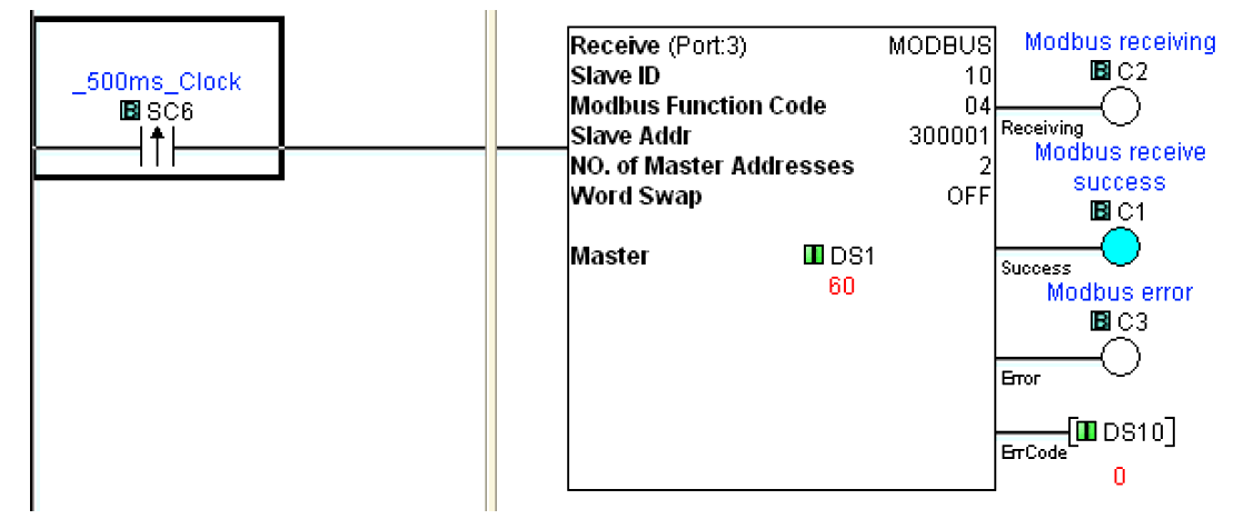
Here, the “Receive” instruction in the PLC sends a Modbus function code 04 to read two analog input registers inside the slave device, that slave device being the Emerson Smart Wireless Gateway (Modbus address 10 on this particular EIA/TIA-485 network).
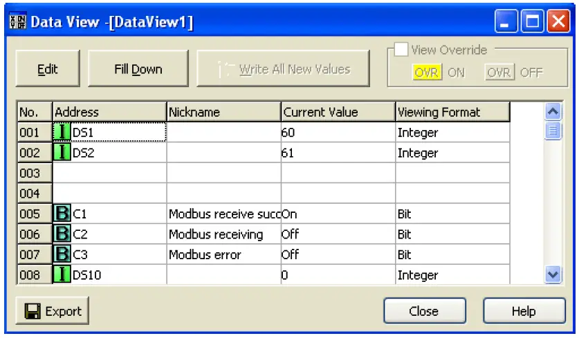
The result of this Modbus query is shown in the next screenshot, where the “Data View” window of the PLC is configured to display the two integer values obtained from the Modbus 04 command. These integer values (stored to registers DS1 and DS2 inside the PLC’s memory) happen to be 60 and 61, representing 60 degrees Fahrenheit and 61 degrees Fahrenheit, respectively. The two temperature transmitters happened to be measuring outdoor ambient temperature at the time this screenshot was taken:
Now that the temperature data resides in the PLC registers, the PLC may be programmed to take action on this data. For example, the PLC may be programmed to turn on cooling fans when the temperatures exceed pre-set limits.
Many modern HMI (Human-Machine Interface) display panels are also capable of serving as Modbus master devices, and may directly read from and write to the network gateway without the need of a PLC. For WirelessHART systems requiring no automatic control (i.e. monitoring and/or manual control functions only) interfacing an HMI panel to the gateway is a simple and practical solution.