Electromagnetic interference problems can arise anywhere since electromagnetic energy can unpredictably couple into systems, producing unwanted effects.
Electromagnetic interference occurs when three elements come together:
- a source of interference
- a receiver of the interference
- a path of transfer
According to this simple scheme, minimizing the electromagnetic interference can be attained by eliminating one of the three elements:
- suppressing the source
- protecting the receiver against noise
- reducing the interference transmission
Any device which suppresses noise between the source and the receiver acts as an EMI shield.
Interferences can propagate in different ways:
By radiation as an electromagnetic wave in free space. Suppression then requires shielding with conductive or absorbing materials.
By conduction via a conductive path. The suppression solution is ferrites in the form of beads or cable shields
Conductive coupling is the most common way an interference signal is transmitted to a system. When studying an interference problem, very often attention is focused on critical components, while system cables are overlooked. A cable can pick up some noise and bring it to other areas traversed by the cable.
There is a need to suppress common mode EMI not only on internal, but also on external cables of electronic equipment.
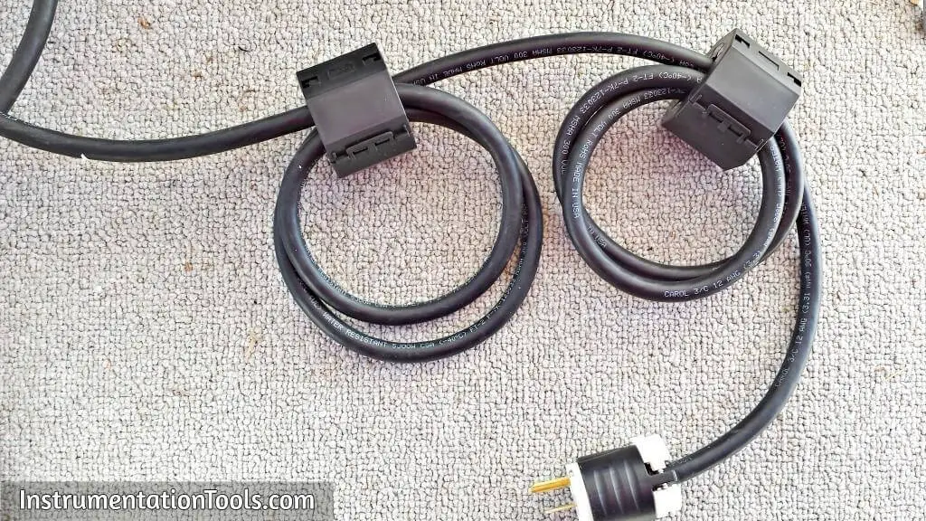
There are tubular cable shields for coaxial cable and rectangular cores for flat ribbon cables. Also split types for retrofit solutions are available. These EMI products provide a high impedance level over a wide frequency range. Ferrite cable shields are cost-effective, as they suppress any electromagnetic noise and reduce the need for other, more complicated, shielding measures.
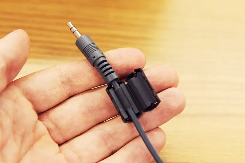
EMI suppression and cable shielding with ferrites
Ferrite shields provide an excellent method to suppress conducted interferences on cables. Cables can act as antennas and radiate RFI power at frequencies above 30MHz. They are a cost-effective alternative to other suppression solutions, like EMI filters or complete shielding.
Applications for cable shielding are found in telecommunication, instrumentation, electronic data processing (EDP) in places like:
- Internal and external computer data cables (for monitors, printers, CPU, keyboards…)
- Internal and external power cables
- Communication cables
- Cables between PC board and data connectors.
Low frequency signals are not affected by a cable shield. At low frequencies a ferrite core causes a low-loss inductance, resulting in a minor increase of impedance (Z=ωL). Interferences normally occur at elevated frequencies and there the picture changes. Magnetic losses start to increase and at the frequency of the so called ferrimagnetic resonance permeability drops rapidly to zero while the impedance reaches a maximum. This impedance, the most important parameter for suppression, becomes almost completely resistive and at very high frequencies even capacitive with losses. While for inductor applications the operating frequency should stay well below the resonance, effective interference suppression is achieved up to much higher frequencies. The impedance peaks at the resonance frequency and the ferrite is effective in a wide frequency band around it.
Around its ferrimagnetic resonance the impedance of a ferrite core is largely resistive, which is a favourable characteristic for several reasons:
- A low-loss inductor can resonate with a capacitance in series, leading to almost zero impedance and interference amplification. A more resistive impedance cannot resonate and is reliable independent of source and load impedances.
- A resistive impedance dissipates interfering signals rather than reflecting them to the source. Oscillations at high frequency can damage semiconductors or affect circuit operation and therefore it is better to absorb them.
- The shape of the impedance curve changes with material losses. A lossy material will show a smooth variation of impedance with frequency and a real wideband attenuation. Interference signals often occur in a broad spectrum
Often EMI suppression is required on cables carrying DC or AC power. In that case current compensation is needed to avoid saturation of the ferrite which would result in loss of impedance. Current compensation is based on the principle that in cables passing through a ferrite core the carried load and signal currents are generally balanced. These currents generate opposed fluxes of equal magnitude that cancel out and no saturation occurs. EMI signals however usually travels in the same direction on all conductors (common mode). They cause flux in the ferrite and will be suppressed by the increased impedance. For high frequency signals, current compensation is a beneficial effect for other reasons than saturation. In an I/O cable the regular RF signal could be suppressed together with the interference. Since the actual signal is differential mode, current compensation avoids this unwanted damping effect on the actual signal.
A cable shield is mainly active against common-mode interference, although its small stray inductance will also have some effect against differential-mode interference. Ferrite products for cable shielding are available in different shapes and can be:
• Entire, for mounting during manufacturing.
Ferrite cores can for instance be embedded in the plastic cover of the cable or shifted on before mounting the connectors.
• Split, for mounting on existing cables.
This type of product was developed for easy installation when the interference problem is detected after final design. The gap between halves has only little influence on the magnetic performance. Impedance is hardly affected, while current handling capability increases. The two halves are mounted with special clips or plastic cases.
Ferrite selection
When selecting a ferrite cable shield to solve an interference problem it is necessary to consider some important application aspects:
• The frequency were maximum attenuation is needed will determine material requirements. The most suitable ferrite would offer the highest impedance levels at the interference frequencies, which usually cover a broad spectrum.
• Core shape, which is usually defined by the cable type.
• Installation requirements to decide on an entire or split core type.
• Attenuation/impedance level for maximum suppression.
• Ferrite characteristics as a function of operating conditions. Impedance can vary with temperature or DC current


Can I get any books related to all instruments and instrumentation
Spelling omission:
“The frequency were maximum attenuation is needed”
I think where.