Inst ToolsInst ToolsInst Tools
  • Courses
  • Automation
    • PLC
    • Control System
    • Safety System
    • Communication
    • Fire & Gas System
  • Instrumentation
    • Design
    • Pressure
    • Temperature
    • Flow
    • Level
    • Vibration
    • Analyzer
    • Control Valve
    • Switch
    • Calibration
    • Erection & Commissioning
  • Interview
    • Instrumentation
    • Electrical
    • Electronics
    • Practical
  • Q&A
    • Instrumentation
    • Control System
    • Electrical
    • Electronics
    • Analog Electronics
    • Digital Electronics
    • Power Electronics
    • Microprocessor
  • Request
Search
  • Books
  • Software
  • Projects
  • Process
  • Tools
  • Basics
  • Formula
  • Power Plant
  • Root Cause Analysis
  • Electrical Basics
  • Animation
  • Standards
  • 4-20 mA Course
  • Siemens PLC Course
Reading: Why is IGBT used in VFD?
Share
Font ResizerAa
Inst ToolsInst Tools
Font ResizerAa
  • Courses
  • Design
  • PLC
  • Interview
  • Control System
Search
  • Courses
  • Automation
    • PLC
    • Control System
    • Safety System
    • Communication
    • Fire & Gas System
  • Instrumentation
    • Design
    • Pressure
    • Temperature
    • Flow
    • Level
    • Vibration
    • Analyzer
    • Control Valve
    • Switch
    • Calibration
    • Erection & Commissioning
  • Interview
    • Instrumentation
    • Electrical
    • Electronics
    • Practical
  • Q&A
    • Instrumentation
    • Control System
    • Electrical
    • Electronics
    • Analog Electronics
    • Digital Electronics
    • Power Electronics
    • Microprocessor
  • Request
Follow US
All rights reserved. Reproduction in whole or in part without written permission is prohibited.
Inst Tools > Blog > Electrical Basics > Why is IGBT used in VFD?

Why is IGBT used in VFD?

In this article, you will learn why is IGBT used in VFD drive. IGBT means Insulated Gate Bipolar Transistor.

Last updated: April 18, 2023 11:18 am
Viral Nagda
Electrical Basics
2 Comments
Share
5 Min Read
SHARE

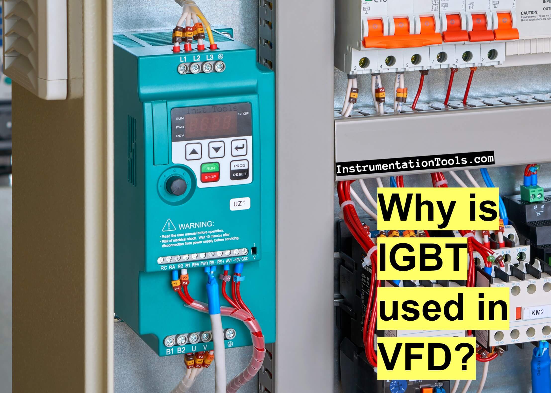
The variable frequency drive (VFD) is a very important equipment in industrial automation. As it is used to vary the speed of the motor, it is applicable in many processes. This is because variable speed is required in almost all applications.

Contents
What is IGBT?Why is IGBT used in VFD?

VFD has many components inside it and semiconductors are extensively used in its design. One such semiconductor is IGBT. We all know how semiconductors play an important role in fast processing.

In this post, we will learn the role of IGBT in VFD.

What is IGBT?

IGBT is a type of transistor. Basically, the family of transistors consists of three main types – BJT (Bipolar Junction Transistor), FET (Field Effect Transistor), and IGBT (Insulated Gate Bipolar Transistor).

IGBT is a more advanced type of transistor. The standard transistor has three terminals – gate, collector, and emitter.

When voltage is applied to the gate, it opens and allows the current to flow between the collector and emitter. When voltage is removed from the gate, it closes and blocks the current to flow between the collector and emitter.

In this way, an IGBT behaves like a switch; on when the gate is open and flowing current and off when it is closed.

IGBT is a combination of BJT and FET. It has the gate function of FET and the low saturation voltage/output characteristics of a BJT. That is why you can see it in its name too; it is a combination of both FET (IG) and BJT (BT). It is capable of handling large collector-emitter currents with virtually zero gate current drive.

Why is IGBT used in VFD?

Why is IGBT used in VFD

 Coming to the main topic, it must be confusing for you because each type of transistor has its separate characteristics. But, it is important to know that the highest level of advantages are offered in an IGBT.

Let us understand step by step why an IGBT is used in VFD.

  1. VFD is used to provide variations in voltage and frequency to control the motor speed. The IGBT, acting as a switch, can create pulsating waveforms known as pulse width modulation (PWM) waveforms at a rapid pace. The switching rate of the IGBT can be controlled depending on the desired output. If the gate is opened and closed slowly, a slow frequency is obtained, while a fast frequency is obtained if the gate is opened and closed quickly. This is the first basic requirement of a VFD. And you get this easily from an IGBT.
  2. Now, let us focus on the main advantages of an IGBT over other semiconductors. BJT can be used at higher voltages, but it has a slow switching frequency. MOSFET can be used at higher switching frequencies, but it has a lower voltage rating. But, IGBT can be used at both higher voltages and higher frequencies. Continuing this, IGBT can thus be used for higher collector current exceeding 100A. And if this is inadequate, two or more IGBTs may be paralleled quite easily.
  3.  The voltage drop and conduction loss are lesser in IGBT as compared to other semiconductors.
  4. The IGBT has a much lower “on-state” resistance, RON than an equivalent MOSFET. This means that the I2R drop across the bipolar output structure for a given switching current is much lower. This means that it has a much lower on-state channel resistance than a standard MOSFET; which automatically increases the current ratings.
  5. The IGBT has a fast switching speed. This minimizes switching losses and allows for high switching frequencies which are good for motor harmonic and noise reduction.
  6. A VFD IGBT can turn ON in less than 400 nanoseconds and OFF in less than 500 nanoseconds. See how fast it can work.

In this way, we understand the use of IGBT in a VFD.

If you liked this article, then please subscribe to our YouTube Channel for Electrical, Electronics, Instrumentation, PLC, and SCADA video tutorials.

You can also follow us on Facebook and Twitter to receive daily updates.

Read Next:

  • What is a Buchholz Relay?
  • Importance of Neutral Wire
  • Induction Motor Problems
  • Cables between VFD & Motor
  • What is a Current Transformer?
Don't Miss Our Updates
Be the first to get exclusive content straight to your email.
We promise not to spam you. You can unsubscribe at any time.
Invalid email address
You've successfully subscribed !

Continue Reading

VFD Pros and Cons – Variable Frequency Drives
What is the LBB Protection Relay? (Local Breaker Backup)
Difference Between Open Circuit and Close Circuit
What is a Magnetic Contactor? – Principle, Types, Advantages
Lithium-ion Battery Charging Systems
How to Locate Faults in Cables? – Fault Analysis & Location
Share This Article
Facebook Whatsapp Whatsapp LinkedIn Copy Link
Share
2 Comments
  • R s rao says:
    December 29, 2022 at 11:41 am

    Lucid writeup.

    Regards

    Reply
  • Matthias says:
    December 30, 2022 at 6:59 pm

    Nice write-up. I design industrial-grade VFDs

    Reply

Leave a Reply Cancel reply

Your email address will not be published. Required fields are marked *

Stay Connected

128.3kFollowersLike
69.1kFollowersFollow
210kSubscribersSubscribe
38kFollowersFollow

Categories

Explore More

Polarization Index (PI) Test and DA Test
Benefits of SIMOCODE over Intelligent MCC
Variable Motor Speed Control
Things to Know When Measuring Voltage
Why is Motor Control Required in Control Systems?
What is Electrical Slip Ring? Principle, Types, Advantages, Applications
What is a Damper? Types of Dampers in HVAC
How does a Lead Acid Battery Work?

Keep Learning

Pros and Cons of Soft Starter

Pros and Cons of Soft Starter

Motor Protection Relay

Motor Protection Circuits

Typical Switchyard Layout

Electrical Substation – Busbar Arrangements and Layouts

VFD Engineer Roles - Installation and Commissioning

VFD Engineer Roles – Installation and Commissioning

Totally Enclosed Fan Cooled (TEFC) Motor

Totally Enclosed Fan Cooled (TEFC) Motors Rampant Winding Burnouts

Electrical Contactor, Switch, Circuit Breaker

Electrical Contactor, Switch, Circuit Breaker

Comparison of Electrical Protection Relays

Comparison of Electrical Protection Relays

Instrument Cable

Difference Between Power Cable and Instrument Cable

Learn More

Smart Sensors in Industry

Smart Sensors in Industry – Components, Types, Advantages

PLC Project Examples for EcoStruxure Machine Expert

PLC Project Examples for EcoStruxure Machine Expert

Temperature Coefficient of Resistance

Temperature Coefficient of Resistance (α)

Three Wire RTD Temperature Compensation

Ambient Temperature Effects on RTD

De-energized Electrical Circuits

De-energized Electrical Circuits, Networks, and Equipment

Calculate the Thermocouple’s Measurement Junction Temperature

Calculate the Thermocouple’s Measurement Junction Temperature

What is Temperature

What is Temperature ?

Digital Electronics MCQ

Digital Integrated Circuits Objective Questions – Part 2

Menu

  • About
  • Privacy Policy
  • Copyright

Quick Links

  • Learn PLC
  • Helping Hand
  • Part Time Job

YouTube Subscribe

Follow US
All rights reserved. Reproduction in whole or in part without written permission is prohibited.
Welcome Back!

Sign in to your account

Username or Email Address
Password

Lost your password?