Inst ToolsInst ToolsInst Tools
  • Courses
  • Automation
    • PLC
    • Control System
    • Safety System
    • Communication
    • Fire & Gas System
  • Instrumentation
    • Design
    • Pressure
    • Temperature
    • Flow
    • Level
    • Vibration
    • Analyzer
    • Control Valve
    • Switch
    • Calibration
    • Erection & Commissioning
  • Interview
    • Instrumentation
    • Electrical
    • Electronics
    • Practical
  • Q&A
    • Instrumentation
    • Control System
    • Electrical
    • Electronics
    • Analog Electronics
    • Digital Electronics
    • Power Electronics
    • Microprocessor
  • Request
Search
  • Books
  • Software
  • Projects
  • Process
  • Tools
  • Basics
  • Formula
  • Power Plant
  • Root Cause Analysis
  • Electrical Basics
  • Animation
  • Standards
  • 4-20 mA Course
  • Siemens PLC Course
Reading: What is a Square Root Extractor? – DP Flow Measurement
Share
Font ResizerAa
Inst ToolsInst Tools
Font ResizerAa
  • Courses
  • Design
  • PLC
  • Interview
  • Control System
Search
  • Courses
  • Automation
    • PLC
    • Control System
    • Safety System
    • Communication
    • Fire & Gas System
  • Instrumentation
    • Design
    • Pressure
    • Temperature
    • Flow
    • Level
    • Vibration
    • Analyzer
    • Control Valve
    • Switch
    • Calibration
    • Erection & Commissioning
  • Interview
    • Instrumentation
    • Electrical
    • Electronics
    • Practical
  • Q&A
    • Instrumentation
    • Control System
    • Electrical
    • Electronics
    • Analog Electronics
    • Digital Electronics
    • Power Electronics
    • Microprocessor
  • Request
Follow US
All rights reserved. Reproduction in whole or in part without written permission is prohibited.
Inst Tools > Blog > Flow Measurement > What is a Square Root Extractor? – DP Flow Measurement

What is a Square Root Extractor? – DP Flow Measurement

In the olden days of DP Flow Measurement, the square-root function was performed in a separate device called a square root extractor.

Last updated: November 2, 2023 12:16 pm
Editorial Staff
Flow Measurement
No Comments
Share
4 Min Read
SHARE

The relationship between flow rate and differential pressure for any fluid-accelerating flow element is non-linear. When plotted on a graph, the relationship between flow rate (Q) and differential pressure (∆P) is quadratic, like one-half of a parabola.

Contents
Relationship of Flow rate and Differential pressureSquare Root ExtractorInternal Parts of Square-root ExtractorPneumatic Square Root Relay

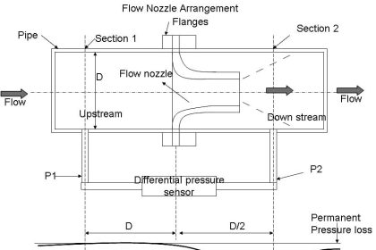
Differential pressure developed by a venturi, orifice plate, pitot tube, or any other acceleration-based flow element is proportional to the square of the flow rate:

Relationship of Flow rate and Differential pressure

Differential Pressure Transmitter Square-root

The traditional means of implementing the necessary signal characterization was to install a “square root” function relay between the transmitter and the flow indicator, as shown in the following diagram:

Square root extractor for DP flow measurement

Square Root Extractor

In the days of pneumatic instrumentation, this square-root function was performed in a separate device called a square root extractor.

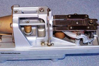
The Foxboro model 557 (2) and Moore Products Model 65 (1) pneumatic square root extractors are classic examples of this technology :

What is Square root extractor

Internal Parts of Square-root Extractor

Square root extractor Parts

Pneumatic square root extraction relays provide a square-root function that the relays were able to serve their purpose in characterizing the output flow signal of a pressure sensor to yield a signal representing flow rate.

Pneumatic Square Root Relay

The following table shows the ideal response of a pneumatic square root relay:

pneumatic square root relay

As you can see from the table, the square-root relationship is most evident in comparing the input and output percentage values.

For example, at an input signal pressure of 6 PSI (25%), the output signal percentage will be the square root of 25%, which is 50% (0.5 = √0.25) or 9 PSI as a pneumatic signal.

At an input signal pressure of 10 PSI (58.33%), the output signal percentage will be 76.38%, because of 0.7638 = √0.5833, yielding an output signal pressure of 12.17 PSI.

When graphed, the function of a square-root extractor is precisely opposite (inverted) of the quadratic function of a flow-sensing element such as an orifice plate, venturi, or pitot tube:

flow-sensing element

When we connect the output of the DP transmitter to the input of Square Root Extractor, the square-root function applies to the output signal – the result is an output signal that tracks linearly with flow rate (Q).

An instrument connected to the square root relay’s signal will, therefore, register the flow rate as it should.

Note: We are not using the square-root extractor devices anymore, these are replaced with modern DP Transmitters.

The modern solution to this problem is to incorporate square-root signal characterization either inside the transmitter or inside the receiving instrument (e.g. indicator, recorder, or controller).

Either way, the square-root function must be implemented somewhere in the loop in order that flow may be accurately measured throughout the operating range.

Read: Square-root in DCS or Transmitter?

Author: Tony R. Kuphaldt

If you liked this article, then please subscribe to our YouTube Channel for Instrumentation, Electrical, PLC, and SCADA video tutorials.

You can also follow us on Facebook and Twitter to receive daily updates.

Read Next:

  • Flow Meter Calibration
  • Averaging Pitot Tube
  • Flow Meter Verification
  • MPFM Working Principle
  • Flow Transmitter Questions
Don't Miss Our Updates
Be the first to get exclusive content straight to your email.
We promise not to spam you. You can unsubscribe at any time.
Invalid email address
You've successfully subscribed !

Continue Reading

Measure Flow rate using Level Sensors
Annubar Flow Meter – Principle, Advantages, Disadvantages
Transit Time Flow Meter – Types, Advantages, Disadvantages
Flow Meter Questions and Answers
Short Notes on Differential Pressure Flow Meters
Flow Switch : What is it? – Applications
Share This Article
Facebook Whatsapp Whatsapp LinkedIn Copy Link
Share
Leave a Comment

Leave a Reply Cancel reply

Your email address will not be published. Required fields are marked *

Stay Connected

128.3kFollowersLike
69.1kFollowersFollow
210kSubscribersSubscribe
38kFollowersFollow

Categories

Explore More

Flow Meter Installation Guidelines
Magnetic Flow Meter Corrosion Effects
Flow Transmitters Questions and Answers – Instruments Test
Impeller Flow Sensor Working Principle and Animation
Difference between Orifice & Restriction Orifice
Vortex Flow meter Animation
Basics of Flow Measurement
Interview Questions on Flow Measurement

Keep Learning

Flow Switch Symbol

Principle of Flow Switch

rangeability-of-flow-meter-vs-percentage-of-maximum-flow

Flow Transmitter Rangeability

Heat Tracing Problems

Heat Tracing Problems

Orifice plate with vent and drain holes

Basics of Orifice Plates

multiphase-flowmeter-working-principle

What are Multiphase Flow Meters? – Working Principle, Advantages

Reciprocating Piston Meters

Overview of Positive Displacement Flow Meters

Oval Gear Flow Meter Principle

Oval Gear Flow Meters – Principle, Advantages, Animation

Impulse line - Purpose & Tapping Point Location

Impulse Line – Purpose & Tapping Point Location

Learn More

Classification of Fuses

Step-by-Step Guide to Choose Right Fuse for a Panel

surface-mounted water pump

Surface-mounted Water Pump

Cell Constant in Conductivity Analyzer

What is Cell Constant in Conductivity Analyzer? and its Importance

Electronic Devices & Circuits Objective Questions

Electronic Devices & Circuits Quiz – Set 13

Difference between Motion Controller and PLC

Difference between Motion Controller and PLC

Instrumentation and Process Control Project Inputs

Instrumentation and Process Teams Interactions in Design Engineering Companies

Basic DC Power Supply Circuit

Basic DC Power Supply Circuit

ESD System Insights

ESD System Insights: Signals for Emergency Valve Shutdown Explained

Menu

  • About
  • Privacy Policy
  • Copyright

Quick Links

  • Learn PLC
  • Helping Hand
  • Part Time Job

YouTube Subscribe

Follow US
All rights reserved. Reproduction in whole or in part without written permission is prohibited.
Welcome Back!

Sign in to your account

Username or Email Address
Password

Lost your password?