Inst ToolsInst ToolsInst Tools
  • Courses
  • Automation
    • PLC
    • Control System
    • Safety System
    • Communication
    • Fire & Gas System
  • Instrumentation
    • Design
    • Pressure
    • Temperature
    • Flow
    • Level
    • Vibration
    • Analyzer
    • Control Valve
    • Switch
    • Calibration
    • Erection & Commissioning
  • Interview
    • Instrumentation
    • Electrical
    • Electronics
    • Practical
  • Q&A
    • Instrumentation
    • Control System
    • Electrical
    • Electronics
    • Analog Electronics
    • Digital Electronics
    • Power Electronics
    • Microprocessor
  • Request
Search
  • Books
  • Software
  • Projects
  • Process
  • Tools
  • Basics
  • Formula
  • Power Plant
  • Root Cause Analysis
  • Electrical Basics
  • Animation
  • Standards
  • 4-20 mA Course
  • Siemens PLC Course
Reading: What is Seal-in Circuit ?
Share
Font ResizerAa
Inst ToolsInst Tools
Font ResizerAa
  • Courses
  • Design
  • PLC
  • Interview
  • Control System
Search
  • Courses
  • Automation
    • PLC
    • Control System
    • Safety System
    • Communication
    • Fire & Gas System
  • Instrumentation
    • Design
    • Pressure
    • Temperature
    • Flow
    • Level
    • Vibration
    • Analyzer
    • Control Valve
    • Switch
    • Calibration
    • Erection & Commissioning
  • Interview
    • Instrumentation
    • Electrical
    • Electronics
    • Practical
  • Q&A
    • Instrumentation
    • Control System
    • Electrical
    • Electronics
    • Analog Electronics
    • Digital Electronics
    • Power Electronics
    • Microprocessor
  • Request
Follow US
All rights reserved. Reproduction in whole or in part without written permission is prohibited.
Inst Tools > Blog > Animation > What is Seal-in Circuit ?

What is Seal-in Circuit ?

Last updated: March 4, 2021 4:33 pm
Editorial Staff
Animation PLC Tutorials
2 Comments
Share
3 Min Read
SHARE

A Seal-in circuit is a method of maintaining current flow after a momentary switch has been pressed and released.

Contents
What is Seal-in Circuit ?PLC Latching Animation

What is Seal-in Circuit ?

Seal in Circuit working

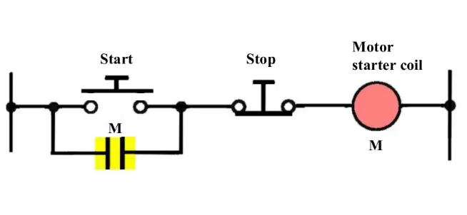
Fig 1 : Start button not pressed

Note : Consider a Relay is used to control the power supply to a motor. Here we are calling this relay as ” Motor Starter Coil “. This Relay another NO contact is used to seal-in or latch the start signal.

As start push button is a push & Release type i.e. signal will be available for some time say momentarily and then signal will be lost.

so we have to latch this circuit in order to make motor run continuously even after release of start push button.

For this purpose we are using Relay (M) NO contact across Start push button such that it will take care of start signal after start button is released.

The seal-in auxiliary contact (NO Contact) of the starter (M) is connected in parallel with the start button to keep the starter coil (M) energized when the start button released.

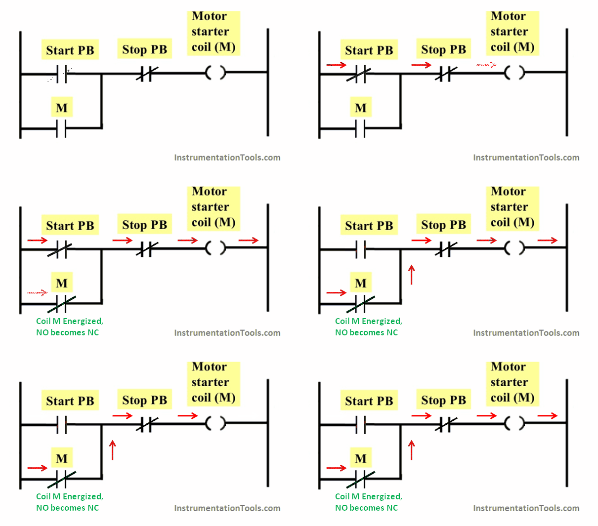
After Start Push button pressed : The Motor starter coil energized and its NO contact becomes NC as shown in below figure.
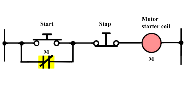
Seal-in Circuit

Fig 2 : Start button pressed

PLC Latching Animation

Start Button Not Pressed :
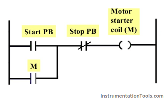
PLC Latching Circuit

Start Button Pressed & Released : 

PLC Latching circuit Animation

During Starting, Start push button will give the signal to energize the coil (M), after that coil NO contact which is connected across

Start Push button will be used to latch the start signal as start push button will be released after pressing ( start button are momentary type ).

Also see : Relay Schematic Animation

If you liked this article, then please subscribe to our YouTube Channel for PLC and SCADA video tutorials.

You can also follow us on Facebook and Twitter to receive daily updates.

Read Next:
  • Latched and Momentary Operation of Motor PLC Program
  • Push button Motor PLC Logic
  • Latches Objective Questions
  • PLC Automatic Control of Two Outputs with one Input
  • Solenoid Operated Valves and Latching Valves
Don't Miss Our Updates
Be the first to get exclusive content straight to your email.
We promise not to spam you. You can unsubscribe at any time.
Invalid email address
You've successfully subscribed !

Continue Reading

SCADA Software and their Comparison
Siemens PLC Course for Beginners: Problems and Solutions
Potentiometer Working Principle Animation
What is Process Control?
Chemical Mixing Process using PLC
Down Counter PLC Program
Share This Article
Facebook Whatsapp Whatsapp LinkedIn Copy Link
Share
2 Comments
  • Trojan says:
    February 17, 2022 at 4:07 pm

    Hi, there is wrong placement of the stop button. The relay will remain latched even when you press the stop button.

    Reply
    • Jeremy Morissette says:
      November 26, 2023 at 11:33 pm

      I had the same thought

      Reply

Leave a Reply Cancel reply

Your email address will not be published. Required fields are marked *

Stay Connected

128.3kFollowersLike
69.1kFollowersFollow
210kSubscribersSubscribe
38kFollowersFollow

Categories

Explore More

PLC Ladder Logic Example
Latched and Momentary Operation of Motor PLC Program
User Defined Data Types (UDT) – Purpose, Need, Tutorial
Siemens PLC Organization Blocks (OB)
Automatic Motor Forward and Reverse Control using Timer
How to Add Unspecified CPU in Tia Portal?
ICS System Design Considerations
Waste-Burning System OMRON PLC Program Example

Keep Learning

Perfume filling system PLC program

CX Programmer Example: Perfume Mixing and Filling System

PLC Motor Logic with START, STOP, TEST Push buttons

PLC Motor Logic with START, STOP, TEST Push buttons

How to Program Sequential Outputs in PLC

Timer-Based Sequential PLC Program with One Button

PLC Count values higher than 999

PLC Count values higher than 999

Structured Text PID control loop in PLC

How to Program PID Control in PLC with Structured Text?

Download Modscan software

How to Use ModScan Software for Testing Modbus Communication?

ControlLogix 5580 Controllers

Rockwell PLCs for Large Scale Applications

Causes of PLC Stop Mode

Various Causes for PLC Going in Stop Mode

Learn More

Heat Recovery in HVAC System

Heat Recovery in HVAC System

IPv4 vs IPv6 - What’s the Difference Between IP addresses

IPv4 vs IPv6 – What’s the Difference Between IP addresses?

Insulators, Conductors and Semiconductors

Why Starting Current of Induction Motor is High

Bottle’s Capping with Rotating Mechanism

PLC FBD Program for Bottle’s Capping with Rotating Mechanism

Arc Fault Breaker (AFB) Electrical Problem Solved

Premature Arc Fault Breaker Failures

Instrument Control Package (ICP)

Package Control and Safety Systems Implementation Methods

Batch mixing process automation with Omron PLC

Automate Batch Mixing with Repeated Cycles in Omron PLC

Menu

  • About
  • Privacy Policy
  • Copyright

Quick Links

  • Learn PLC
  • Helping Hand
  • Part Time Job

YouTube Subscribe

Follow US
All rights reserved. Reproduction in whole or in part without written permission is prohibited.
Welcome Back!

Sign in to your account

Username or Email Address
Password

Lost your password?