Inst ToolsInst ToolsInst Tools
  • Courses
  • Automation
    • PLC
    • Control System
    • Safety System
    • Communication
    • Fire & Gas System
  • Instrumentation
    • Design
    • Pressure
    • Temperature
    • Flow
    • Level
    • Vibration
    • Analyzer
    • Control Valve
    • Switch
    • Calibration
    • Erection & Commissioning
  • Interview
    • Instrumentation
    • Electrical
    • Electronics
    • Practical
  • Q&A
    • Instrumentation
    • Control System
    • Electrical
    • Electronics
    • Analog Electronics
    • Digital Electronics
    • Power Electronics
    • Microprocessor
  • Request
Search
  • Books
  • Software
  • Projects
  • Process
  • Tools
  • Basics
  • Formula
  • Power Plant
  • Root Cause Analysis
  • Electrical Basics
  • Animation
  • Standards
  • 4-20 mA Course
  • Siemens PLC Course
Reading: Working of Rupture Disk
Share
Font ResizerAa
Inst ToolsInst Tools
Font ResizerAa
  • Courses
  • Design
  • PLC
  • Interview
  • Control System
Search
  • Courses
  • Automation
    • PLC
    • Control System
    • Safety System
    • Communication
    • Fire & Gas System
  • Instrumentation
    • Design
    • Pressure
    • Temperature
    • Flow
    • Level
    • Vibration
    • Analyzer
    • Control Valve
    • Switch
    • Calibration
    • Erection & Commissioning
  • Interview
    • Instrumentation
    • Electrical
    • Electronics
    • Practical
  • Q&A
    • Instrumentation
    • Control System
    • Electrical
    • Electronics
    • Analog Electronics
    • Digital Electronics
    • Power Electronics
    • Microprocessor
  • Request
Follow US
All rights reserved. Reproduction in whole or in part without written permission is prohibited.
Inst Tools > Blog > Control Valves > Working of Rupture Disk

Working of Rupture Disk

Last updated: March 21, 2019 11:42 pm
Editorial Staff
Control Valves
2 Comments
Share
4 Min Read
SHARE

A Rupture Disk is a non-reclosing pressure relief device actuated by static differential pressure between the inlet and outlet of the device and designed to function by the bursting of a rupture disk.

Contents
What is Rupture Disk ?Terms Related with Rupture Disc:

A rupture disk device includes a rupture disk and a rupture disk holder.

What is Rupture Disk ?

A rupture disk holder is the structure which encloses and clamps the rupture disk in Position

What is Rupture Disk ?

Terms Related with Rupture Disc:

Burst Pressure:

The burst pressure of a rupture disk at the specified temperature is the value of the upstream static pressure minus the value of the downstream static pressure just prior to when the disk bursts.

When the downstream pressure is atmospheric, the burst pressure is the upstream static gauge pressure. The specified burst pressure is the burst pressure specified by the user.

Now the manufacturer takes the min of two rupture disc per lot and performs the test.

Here comes the two term Marked burst pressure and Manufacture range.

Marked Burst Pressure:

The marked burst pressure, or rated burst pressure of a rupture disk, is the burst pressure established by tests for the specified temperature and marked on the disk tag by the manufacturer.

Now what value is to be marked? It may be specified burst pressure or any value other than specified burst pressure. It is decided by manufacturer range.

Manufacturer Range:

The manufacturing range is the pressure range in which the rupture disk shall be marked. Manufacturing ranges are usually catalogued by the manufacturer as a percentage of the specified burst pressure. Catalogued manufacturing ranges may be modified by agreement between the user and the manufacturer.

For zero manufacturing range rupture discs, a minimum of two burst tests per lot of rupture discs are conducted to determine conformance with the customer’s specified burst pressure. The rated (stamped) burst pressure appearing on the tag will be the customer’s specified burst pressure.

For rupture discs with -5%, -10%, -2.5psig, or -5 psig manufacturing ranges, the rated (stamped) burst pressure is established by bursting a minimum of two discs per lot and averaging the actual burst results. This average burst pressure is the rated (stamped)

burst pressure which will appear on the rupture disc tag.

Now here it is best to tell about Burst pressure tolerance. Burst pressure tolerances the variation around the Marked burst pressure (not around specified burst pressure ) at the specified disk temperature in which a rupture disk shall burst.

In order to maximize the life of the rupture disc, manufacturer recommends the maximum operating pressure for rupture disc called Maximum Recommended Operating Pressure. Reverse-acting rupture disks provide satisfactory service life when operating pressures are 90% or less of marked burst pressure (90% operating ratio). Consult the manufacturer for the actual recommended operating ratio for the specific disk under consideration.

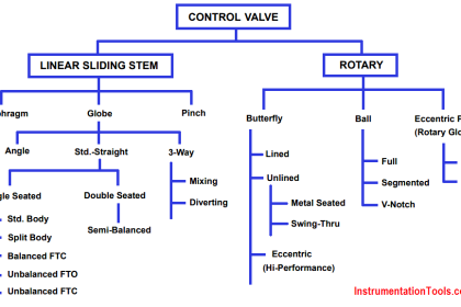
Also Read: Fundamentals of Control Valves

Don't Miss Our Updates
Be the first to get exclusive content straight to your email.
We promise not to spam you. You can unsubscribe at any time.
Invalid email address
You've successfully subscribed !

Continue Reading

Types of Pneumatic Actuators Animation
Snap Acting Relay Working Principle
Trip Valve Principle
Basics of Gate Valves
Identify Valve Parts Quiz with Answers
Control Valve Cv calculation
Share This Article
Facebook Whatsapp Whatsapp LinkedIn Copy Link
Share
2 Comments
  • Jekker says:
    February 8, 2016 at 11:42 pm

    Admin of instrumentationtools.com Excellent & Superb.
    Article useful, the main thing that helped people, Respect to you!

    Reply
  • Imran Malik says:
    December 12, 2021 at 4:50 pm

    Good article, Just wondering what shall be difference between a design fit for Gas and Another for LIQUID service?

    Reply

Leave a Reply Cancel reply

Your email address will not be published. Required fields are marked *

Stay Connected

128.3kFollowersLike
69.1kFollowersFollow
210kSubscribersSubscribe
38kFollowersFollow

Categories

Explore More

Locked Open (LO) and Locked Closed (LC) Valves
Control Valve Flow Direction
Calculate Flow Coefficient Kv of Solenoid Valve
Control Valves Chemical attack Problems
Types of Pilot Operated Diaphragm Solenoid Valve Principle
Self Actuated Pressure Control Valve Principle
Types of Control Valve Trim
Basics of Globe Valves

Keep Learning

Valve Bellows seal

Bellows Seal Valve Working Principle

Procedure for the Repair of Control Valve

Basic Steps and Procedure for the Repair of Control Valve

3-port-2-position-direct-acting-solenoid-valve

3 Port 2 Position Direct Acting Solenoid Valve Working Principle

Dual Solenoid Valve on Control Valve

Why we Require Dual SOV on a Control Valve?

Safety Valve

Compare Relief Valve and Safety Valve

valve-actuator

Pneumatic Control Valve Actuators

Direct operated (direct acting) solenoid valves

Solenoid Valves Types & Functions

Basics of Actuators

Basics of Actuators

Learn More

Butterfly Valve

Butterfly Valves Construction, Types, Stem & Bonnet Assembly

hall effect speed sensor

Speed Probe Working Principle

Installation and Calibration of Pressure Transmitter

Installation and Calibration of Pressure Transmitter

Three Phase Induction Motor Interview Questions & Answers

Three Phase Induction Motor Interview Questions & Answers

Types of Digital Outputs in PLC

Types of Digital Outputs in PLC

Programmable Logic Controller (PLC) Questions and Answers – 9

Differential Pressure Sensor with pair of Strain Gauges

Differential Pressure Sensor with Pair of Strain Gauges

Brands PLC communication interface and protocol

Communicating Between Siemens PLC and Other PLC Brands

Menu

  • About
  • Privacy Policy
  • Copyright

Quick Links

  • Learn PLC
  • Helping Hand
  • Part Time Job

YouTube Subscribe

Follow US
All rights reserved. Reproduction in whole or in part without written permission is prohibited.
Welcome Back!

Sign in to your account

Username or Email Address
Password

Lost your password?