HART Overview
The majority of smart field devices installed worldwide today are HART-enabled. But some new in the automation field may need a refresher on this powerful technology.
Simply put, the HART (Highway Addressable Remote Transducer) Protocol is the global standard for sending and receiving digital information across analog wires between smart devices and control or monitoring system or Handheld communicators.
More specifically, HART is a bi-directional communication protocol that provides data access between intelligent field instruments and host systems (DCS/PLC or Handheld Communicator). A host can be any software application from technician’s hand-held device or laptop to a plant’s process control, asset management, safety or other system using any control platform.
HART Technology
HART technology is easy to use and very reliable when used for commissioning and calibration of smart devices as well as for continuous online diagnostics.
There are several reasons to have a host communicate with smart devices. These include:
Years of success using these benefits explain why HART technology is the largest of all communication protocols, installed in more than 30 million devices worldwide.
If you’ve ever used a land-line telephone and noticed the Caller ID display to take note of who is calling, you already know half of what the HART Protocol does—it tells “who” is calling. In an industrial automation network “who” is a microprocessor-based smart field device. In addition to letting such smart field devices “phone home,” HART Communication lets a host system send data to the smart instrument.
HART emerged in the late1980s based on the same technology that brought Caller ID to analog telephony. It has undergone continued development, up to and including automation products now shipping with built-in WirelessHART Communication.
How HART Works
“HART” is an acronym for Highway Addressable Remote Transducer. The HART Protocol makes use of the Bell 202 Frequency Shift Keying (FSK) standard to superimpose digital communication signals at a low level on top of the 4-20mA.
Frequency Shift Keying
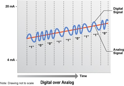
The HART communication protocol is based on the Bell 202 telephone communication standard and operates using the frequency shift keying (FSK) principle. The digital signal is made up of two frequencies— 1,200 Hz and 2,200 Hz representing bits 1 and 0, respectively. Sine waves of these two frequencies are superimposed on the direct current (dc) analog signal cables to provide simultaneous analog and digital communications. Because the average value of the FSK signal is always zero, the 4–20 mA analog signal is not affected. The digital communication signal has a response time of approximately 2–3 data updates per second without interrupting the analog signal. A minimum loop impedance of 230 W is required for communication.
This enables two-way field communication to take place and makes it possible for additional information beyond just the normal process variable to be communicated to/from a smart field instrument. The HART Protocol communicates at 1200 bps without interrupting the 4-20mA signal and allows a host application (master) to get two or more digital updates per second from a smart field device. As the digital FSK signal is phase continuous, there is no interference with the 4-20mA signal.
HART technology is a master/slave protocol, which means that a smart field (slave) device only speaks when spoken to by a master. The HART Protocol can be used in various modes such as point-to-point or multidrop for communicating information to/from smart field instruments and central control or monitoring systems.
HART Communication occurs between two HART-enabled devices, typically a smart field device and a control or monitoring system. Communication occurs using standard instrumentation grade wire and using standard wiring and termination practices.
The HART Protocol provides two simultaneous communication channels: the 4-20mA analog signal and a digital signal. The 4-20mA signal communicates the primary measured value (in the case of a field instrument) using the 4-20mA current loop – the fastest and most reliable industry standard. Additional device information is communicated using a digital signal that is superimposed on the analog signal.
The digital signal contains information from the device including device status, diagnostics, additional measured or calculated values, etc. Together, the two communication channels provide a low-cost and very robust complete field communication solution that is easy to use and configure.
HART Networks
HART devices can operate in one of two network configurations—point-topoint or multidrop.
POINT-TO-POINT
In point-to-point mode, the traditional 4–20 mA signal is used to communicate one process variable, while additional process variables, configuration parameters, and other device data are transferred digitally using the HART protocol (Figure 2). The 4–20 mA analog signal is not affected by the HART signal and can be used for control in the normal way. The HART communication digital signal gives access to secondary variables and other data that can be used for operations, commissioning, maintenance, and diagnostic purposes.
The HART Protocol provides for up to two masters (primary and secondary). This allows secondary masters such as handheld communicators to be used without interfering with communications to/from the primary master, i.e. control/monitoring system.
The HART Protocol permits all digital communication with field devices in either point-to-point or multidrop network configurations:
Multidrop Configuration
There is also an optional “burst” communication mode where a single slave device can continuously broadcast a standard HART reply message. Higher update rates are possible with this optional burst communication mode and use is normally restricted to point-to-point configuration.
The multidrop mode of operation requires only a single pair of wires and, if applicable, safety barriers and an auxiliary power supply for up to 15 field devices. All process values are transmitted digitally. In multidrop mode, all field device polling addresses are >0, and the current through each device is fixed to a minimum value (typically 4 mA).
Communication Modes
1. Master Slave Mode
HART is a master-slave communication protocol, which means that during normal operation, each slave (field device) communication is initiated by a master communication device. Two masters can connect to each HART loop. The primary master is generally a distributed control system (DCS), programmable logic controller (PLC), or a personal computer (PC). The secondary master can be a handheld terminal or another PC. Slave devices include transmitters, actuators, and controllers that respond to commands from the primary or secondary master
2. Burst Mode
Some HART devices support the optional burst communication mode. Burst mode enables faster communication (3–4 data updates per second). In burst mode, the master instructs the slave device to continuously broadcast a standard HART reply message (e.g., the value of the process variable). The master receives the message at the higher rate until it instructs the slave to stop bursting.
DEVICE DESCRIPTION
Some HART host applications use device descriptions (DD) to obtain information about the variables and functions contained in a HART field device. The DD includes all of the information needed by a host application to fully communicate with the field device. HART Device Description Language (DDL) is used to write the DD, that combines all of the information needed by the host application into a single structured file. The DD identifies which common practice commands are supported as well as the format and structure of all device-specific commands. A DD for a HART field device is roughly equivalent to a printer driver for a computer. DDs eliminate the need for host suppliers to develop and support custom interfaces and drivers.
A DD provides a picture of all parameters and functions of a device in a standardized language. HART suppliers have the option of supplying a DD for their HART field product. If they choose to supply one, the DD will provide information for a DD-enabled host application to read and write data according to each device’s procedures.
DD source files for HART devices resemble files written in the C programming language. DD files are submitted to the HCF for registration in the HCF DD Library. Quality checks are performed on each DD submitted to ensure specification compliance, to verify that there are no conflicts with DDs already registered, and to verify operation with standard HART hosts. The HCF DD Library is the central location for management and distribution of all HART DDs to facilitate use in host applications such as PCs and handheld terminals.
Benefits of Using HART
Engineers operating in analog automation environments no longer need utter the words “if only” as in “if only I could get the device information without going into the field” or “if only I could get this configuration information from that pressure transmitter into my PC.”
Users worldwide who have realized the benefits of HART Communication know that they can gain quick, easy visibility to devices in the field when using HART-enabled handheld test, calibration devices and portable computers. In fact, device testing, diagnostics and configuration has never been easier!
However, many have yet to realize HART technology’s greatest benefits which come from full-time connections with real-time asset management and/or control systems.
HART technology can help you:
Increase Plant Availability
Reduce Maintenance Costs
Improve regulatory compliance
The standard features of HART technology range from simple compatibility with existing 4-20mA analog networks to a broad product selection:
HART Protocol Specifications
The HART Protocol was developed in the late 1980’s and transferred to the HART Foundation in the early 1990’s. Since then it has been updated several times. When the protocol is updated, it is updated in a way that ensures backward compatibility with previous versions. The current version of the HART Protocol is revision 7.3. The “7” denotes the major revision level and the “3” denotes the minor revision level.
The HART Protocol implements layers 1,2, 3, 4 and 7 of the Open System Interconnection (OSI) 7-layer protocol model:
The HART Physical Layer is based on the Bell 202 standard, using frequency shift keying (FSK) to communicate at 1200 bps. The signal frequencies representing bit values of 0 and 1 are 2200 and 1200Hz respectively. This signal is superimposed at a low level on the 4-to-20mA analog measurement signal without causing any interference with the analog signal.
The HART Data Link Layer defines a master-slave protocol – in normal use, a field device only replies when it is spoken to. There can be two masters, for example, a control system as a primary master and a handheld HART communicator as a secodary master. Timing rules define when each master may initiate a communication transaction. Up to 15 or more slave devices can be connected to a single multidrop cable pair.
The Network Layer provides routing, end-to-end security, and transport services. It manages “sessions” for end-to-end communication with correspondent devices.
The Transport Layer: The Data-Link Layer ensures communications are successfully propagated from one device to another. The Transport Layer can be used to ensure end-end communication is successful.
The Application Layer defines the commands, responses, data types and status reporting supported by the Protocol. In the Application Layer, the public commands of the protocol are divided into four major groups:
Advanced HART Application
The power of the HART protocol is evident in the control diagram of Below Figure. This innovative application uses the inherent feature of the HART protocol that both 4-20 mA analog and digital communication signals are transmitted simultaneously over the same wiring.
In this application, the HART-compatible transmitter has an internal PID control capability. The device is configured such that the 4-20 mA loop current is proportional to the control output of the PID algorithm executing in the device (not the measured variable as in most transmitter applications). Since the 4-20 mA loop current is regulated by the PID control output, it is used to drive the valve position directly.
The control loop executes entirely in the field between the transmitter (with PID) and the control valve. The control action is continuous as the traditional 4-20 mA analog signal drives the valve. HART digital communication links the operator with the control loop to change set point, and read the primary variable, or valve position output. Substantial savings are possible in applications where this innovative control architecture is appropriate.
The conveyor sorting machine is widely used in the packing industries using the PLC program…
Learn the example of flip-flop PLC program for lamps application using the ladder logic to…
In this article, you will learn the STAR DELTA programming using PLC controller to start…
Lube oil consoles of rotary equipment packages in industrial process plants are usually equipped with…
Rotating equipment packages such as pumps, compressors, turbines need the lube oil consoles for their…
This article explains how to blink lights in ladder logic with a detailed explanation video…


View Comments
Dear Sir,
It was really informative topic put up in a very good manner. Explains a great deal of Grey areas as far as the HART protocol is concerned.
I have a difficulty where in i have a field device which has HART (Active) as output and i need to read the data on DCS or a Recorder with 4-20mA as input. So kindly suggest what interface device i need to use and also state what does HART(Active) mean?
Very informative,all basics details provides in such an manner that anyone can understand.Many doubts clear in single documents.Thanks
¡Buen día!
Requiero saber ¿cuál es la última versión HART en los instrumentos, actualmente?
¡Saludos!
Translated -
Good day!
I need to know what is the latest HART version in the instruments, currently?
Greetings! Thank you for helping me with your information