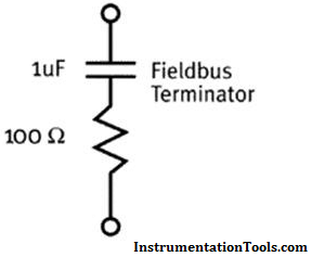
First let’s define exactly what a fieldbus terminator is. A fieldbus terminator is a component of a fieldbus system that is the equivalent of a 1 µF capacitor and a 100 Ω resistor in series with each other. The main functions of fieldbus terminators are to shunt the fieldbus current and to protect the fieldbus signal against electrical reflections.

Each fieldbus segment needs exactly two terminators. These terminators are located at both the beginning of the segment and at the very end of the segment. Many times, the terminator located at the beginning of the segment is built into the fieldbus power supply modules, fieldbus power conditioners, or, in Pepperl+Fuchs’ case, it is built into the motherboard that houses the power supply modules and is activated by a simple switch. All of these methods for adding a terminator work well because they end up saving you from adding components to your overall system topology. The terminators located at the end of the segment are normally added as a standalone component or built into your distribution junction box.
The main purpose of fieldbus terminators is to act as a current shunt for the control network. Fieldbus devices communicate with other devices and the controller by changing their overall current draw. This modulating current passes across the terminators in the segment, resulting in the fieldbus signal voltage. Having too many (three or more) terminators results in a reduction in signal level. One extra terminator in the segment typically reduces the signal by about 30%. Failing to use terminators in your segment has the reverse effect and causes a large increase in signal level; approximately 70% for each missing terminator.
Another function of the terminator is to reduce the impact of electrical reflections.Reflections on a control network are similar to waves in a pool. As a wave propagates through the water, it may come into contact with obstacles such as the side of the pool. When the wave hits the side of the pool, a small part of the wave bounces back towards the origin of the wave. In a fieldbus network, the communication signal is the wave. The side of the pool is represented by inconsistencies in the cabling. These reflected signals could cause problems such as noise, jitter, and inaccurate data. Using a fieldbus terminator at each end of the segment helps to reduce the inconsistency and minimize the portion of the signal that is bounced back.
The terminator is an essential piece of a working fieldbus network. Terminators are a simple, yet extremely crucial component of the overall topology and excluding them from (or adding too many to!) your segment will undoubtedly have a negative impact on your signal level.
Also Read: Profibus Communication Interview Questions
Learn an example PLC program to control a pump based on level sensors using ladder…
In the PLC timer application for security camera recording, when motion is detected then camera…
In this example, we will learn batch mixing with PLC ladder logic program using timer…
This PLC example on manufacturing line assembly is an intermediate-level PLC program prepared for the…
In this article, you will learn the PLC programming example with pushbutton and motor control…
This article teaches how to convert Boolean logic to PLC programming ladder logic with the…
View Comments
Thanks for sharing