Inst ToolsInst ToolsInst Tools
  • Courses
  • Automation
    • PLC
    • Control System
    • Safety System
    • Communication
    • Fire & Gas System
  • Instrumentation
    • Design
    • Pressure
    • Temperature
    • Flow
    • Level
    • Vibration
    • Analyzer
    • Control Valve
    • Switch
    • Calibration
    • Erection & Commissioning
  • Interview
    • Instrumentation
    • Electrical
    • Electronics
    • Practical
  • Q&A
    • Instrumentation
    • Control System
    • Electrical
    • Electronics
    • Analog Electronics
    • Digital Electronics
    • Power Electronics
    • Microprocessor
  • Request
Search
  • Books
  • Software
  • Projects
  • Process
  • Tools
  • Basics
  • Formula
  • Power Plant
  • Root Cause Analysis
  • Electrical Basics
  • Animation
  • Standards
  • 4-20 mA Course
  • Siemens PLC Course
Reading: Voltage Divider Rule
Share
Font ResizerAa
Inst ToolsInst Tools
Font ResizerAa
  • Courses
  • Design
  • PLC
  • Interview
  • Control System
Search
  • Courses
  • Automation
    • PLC
    • Control System
    • Safety System
    • Communication
    • Fire & Gas System
  • Instrumentation
    • Design
    • Pressure
    • Temperature
    • Flow
    • Level
    • Vibration
    • Analyzer
    • Control Valve
    • Switch
    • Calibration
    • Erection & Commissioning
  • Interview
    • Instrumentation
    • Electrical
    • Electronics
    • Practical
  • Q&A
    • Instrumentation
    • Control System
    • Electrical
    • Electronics
    • Analog Electronics
    • Digital Electronics
    • Power Electronics
    • Microprocessor
  • Request
Follow US
All rights reserved. Reproduction in whole or in part without written permission is prohibited.
Inst Tools > Blog > Electronic Devices & Circuits > Voltage Divider Rule

Voltage Divider Rule

Last updated: October 6, 2016 6:45 am
Editorial Staff
Electronic Devices & Circuits
No Comments
Share
1 Min Read
SHARE

It can be quite useful to determine how a voltage appearing across two series resistors “divides” between them.

Consider the circuit shown below:

Voltage Divider Rule

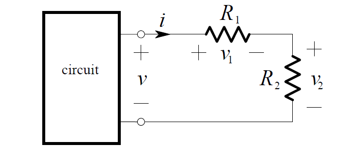
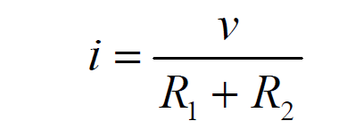
By Ohm’s Law, the current in the resistors is:

current-in-the-resistors

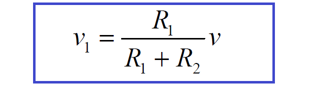
By application of Ohm’s Law again, the voltage across R1  is:

v1 = R1 . i

and therefore:

voltage-divider-rule-formula

Similarly, the voltage across R2  is:

voltage-divider-rule-formula-2

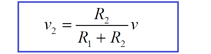
These equations describe how the voltage is divided between the resistors. Because of this, a pair of resistors in series is often called a voltage divider.

Example:

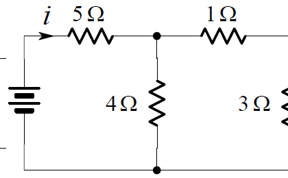
We want to find the voltage v in the circuit below:

voltage-divider-rule-circuit-example

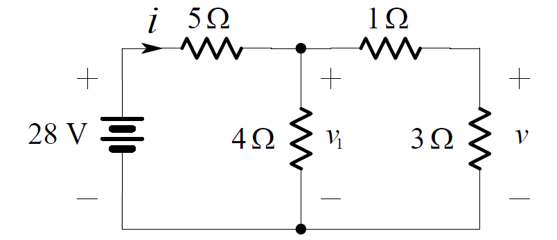
Combining the series connection of the 1 ohm and 3 ohm resistors, we obtain the

voltage-divider-rule-circuit-example-1

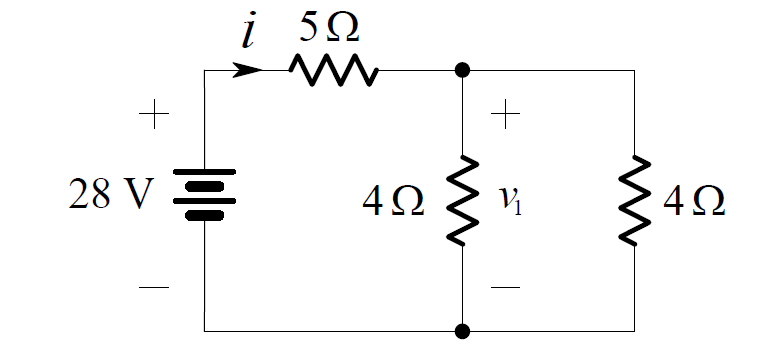
Now the pair of 4 ohms resistors in parallel can be combined as shown below:

voltage-divider-rule-circuit-example-2

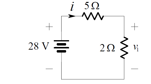
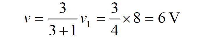
By voltage division:

voltage-divider-rule-circuit-equation

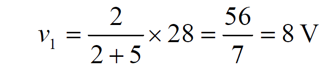
Returning to the original circuit and applying voltage division again yields:

voltage-divider-rule-circuit-equation-1

Don't Miss Our Updates
Be the first to get exclusive content straight to your email.
We promise not to spam you. You can unsubscribe at any time.
Invalid email address
You've successfully subscribed !

Continue Reading

Capacitor Filter Operation
Photodiode Working Principle
Transistor Emitter Feedback Bias
Short Circuit and Open Circuit
Positive & Negative Diode Clippers
Full Wave Rectifier
Share This Article
Facebook Whatsapp Whatsapp LinkedIn Copy Link
Share
Leave a Comment

Leave a Reply Cancel reply

Your email address will not be published. Required fields are marked *

Stay Connected

128.3kFollowersLike
69.1kFollowersFollow
210kSubscribersSubscribe
38kFollowersFollow

Categories

Explore More

Operation of Zener Diode Voltage Regulator
Forward Bias & Reverse Bias of a Diode
Laser Diode Working Principle
Capacitor Filter Working Principle
Transistor as a Switch Working Principle
Diodes Voltage Tripler
Band Gap for Semiconductor Materials
How the Matrix Keypad works with a Micro controller?

Keep Learning

Basic DC Power Supply Circuit

Basic DC Power Supply Circuit

Full Wave Rectifier Peak Inverse Voltage

Full Wave Bridge Rectifier Peak Inverse Voltage

Derivation-of-Ohms-Law

Basics of Ohm’s Law

Bipolar Junction Transistor Construction

Bipolar Junction Transistor Construction

Choke Input Filter Operation

Choke Input Filter Operation

full-wave-bridge-rectifier-with-voltage-regulator

Basics of Voltage Regulators

Transistor Collector Characteristic Curves

Transistor Collector Characteristic Curves

Diode Rectifier

Bridge Rectifier Working Animation

Learn More

Automotive Rail Rapid Transit

Automotive Rail Rapid Transit

Surface Condenser Condensate Evacuation Pumps

Condensate Pump Frequent Wrecks Threatens Long Plant Outages

Field Instrumentation Interview Questions and Answers

Field Instrumentation Interview Questions and Answers

PISTON CHECK VALVE THEORY

Valve Materials Comparison Notes

What is a Current Transformer

What is a Current Transformer?

Density-Measurement-using-DP-Transmitter-for-Closed-Tank-Wet-leg

Density Measurement using DP Transmitter for closed tank with wet leg

pressure transmitter calibration setup

Why Pressure Vessel Connected to Tubing System?

Uncertainty Calculations of Pressure Calibration

Uncertainty Calculations of Pressure Calibration

Menu

  • About
  • Privacy Policy
  • Copyright

Quick Links

  • Learn PLC
  • Helping Hand
  • Part Time Job

YouTube Subscribe

Follow US
All rights reserved. Reproduction in whole or in part without written permission is prohibited.
Welcome Back!

Sign in to your account

Username or Email Address
Password

Lost your password?