In this article, we will take about clock memory bits in TIA Portal and Siemens PLC. And we will show how to enable the use of the memory bits and how it can help you avoid coding a lot of logic lines to obtain a simple function that your PLC already do it internally.
Contents:
A clock memory is a bit memory that changes its binary status periodically in the ratio of 1:1. That simply means it changes its status periodically between true and false with a pre-defined frequency.
There are 8 clock memory bits pre-defined in the CPU which is why they are also called clock memory byte.
You decide which memory byte of the CPU will become the clock memory byte when you enable the use of the memory byte and assign the clock memory parameters.
You don’t necessarily need the clock memory as you can create your own logic and achieve the same functionality. However, it is a good thing to have in your pocket when you need such functionality. As creating 8 separate logic for 8 clock memory bits will take some of your time and effort and might make your program unnecessarily large.
You can use clock memory, for example, to activate flashing indicator lamps or to initiate periodically recurring operations such as recording actual values.
Each bit of the clock bit memory byte is assigned a frequency. See the following table.
| Bit of the clock memory byte | 7 | 6 | 5 | 4 | 3 | 2 | 1 | 0 |
| Period (s) | 2.0 | 1.6 | 1.0 | 0.8 | 0.5 | 0.4 | 0.2 | 0.1 |
| Frequency (Hz) | 0.5 | 0.625 | 1 | 1.25 | 2 | 2.5 | 5 | 10 |
Table 1. Clock memory bits frequencies according to the TIA Portal help manual.
To use the clock memory bits in your logic, you need to enable the use of the clock memory byte from the properties of the CPU. See picture 1.
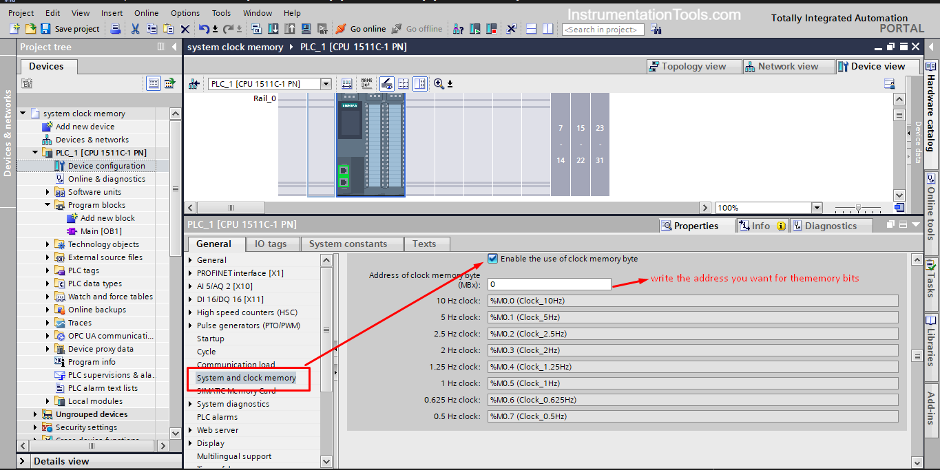
You can choose the address of the byte you want to assign for the clock memory, just make sure it doesn’t conflict with any other memory bytes in your PLC logic.
As you see from the picture, we chose the address 0, so if you need to use the 2Hz clock bit you will use the bit %M0.3
In a previous article, we used a simple example of a conveyor belt moving a product between the start and end of the belt. There was an indication LED that turns ON when the Belt is running. See picture 2.
We will use the same example, but this time we will make the LED more intuitive using the clock memory bits. This time we will use the clock memory bits with the LED to give an indication of different cases of the process.
In a conveyor belt system controlled by a PLC, there are two presence sensors at the two ends of the belt to detect the presence of a product, when the product is detected at the start of the belt, the conveyor can be started through a start Pushbutton and when the product reaches the end the belt will stop automatically and it will not run again until a new product is detected once again at the start and the START push button is pressed.
The indication LED should have more than one behavior depending on the current case of the system.
These cases are as follows:
We have 4 digital inputs as follows:
We also have 2 digital outputs as follows:
First, we select our PLC and assign the IO tags. See picture 3
Don’t forget to enable the use of the clock memory byte as shown in picture 1.
We will have two networks of code, one for the control of the conveyor belt and another for the LED logic. See pictures 4 and 5 for the logic.
As you can see, using the clock memory bits made the logic simple and easy to read. Imagine if you would create the same logic without the use of these bits, you would have used a lot of timers and your logic would have been fairly complicated.
We explained before how to use the PLCSim to simulate our code. In this example, we will use the simulation sequence to create the same sequence of the actual process and we will see if the LED behavior will match the intended functionality or not.
Start by compiling our code and start a new simulation. See picture 6.
As you can see, the LED is now OFF; there are no products presences at the start or the end of the conveyor.
We created a simulation sequence and see how the LED will react to different process conditions. See the following animation.
See if you can notice how the LED behavior changes with different process conditions.
If you liked this article, then please subscribe to our YouTube Channel for Instrumentation, Electrical, PLC, and SCADA video tutorials.
You can also follow us on Facebook and Twitter to receive daily updates.
Read Next:
Omron PLC logic for sorting the number of products and counting the number of products…
Learn the water fountain control logic using the PLC timers programming to control the high…
Open Telemetry is a framework for collecting data in cloud-native applications including tracing, metrics, and…
This article is about controlling the Pneumatic cylinder and Pneumatic motor in the assembly line…
In this post, we will learn the basic requirements for a network switch to be…
The PLC panel and MCC panel interface signals are start, stop, run feedback, trip, local…


