A urea bagging plant is a facility designed to handle the final packaging of urea fertilizer. The Bagging Plant manages to pack Urea pallets with high efficiency and quality received from the Urea Plant after Prilling and Neem Coating.
Urea Bagging Plant
Generally, the following activity is carried out in the Bagging plant.
All activity’s brief detail is listed below:-
- To receive and store the Urea Pallet received from the Urea Plant.
- To Bagg the stored Urea.
- To segregate the defective Urea Pallet and Dust.
- To Bagg the Urea in Urea Bags.
- To perform the sewing of Filled bags neatly and cleanly.
- To load the packed bags in Truck and Loader according to market demand.
In general practice, every plant management avoids storing the Urea Pallet in Urea storage silo and filled Urea bags. Because Urea reclaiming cost from Silo required a lot of energy and not financially beneficial practice.
Therefore in the bagging plant, we continue to receive Urea and in the meantime, we bag it and load it into a Truck or wagon.
Equipment used in the Urea Bagging Plant
The main equipment of a urea bagging plant is as follows.
- Portal Scrapper cum Declaimer (PS-1),
- Bulk Conveyor (BC),
- Flat Conveyor (FC),
- Slat Conveyor (SC),
- Buffer Hopper (BH),
- Magnetic Pully (DF),
- Urea Storage Silo,
- Wet Dust Suppression System (WDS)
Portal Scrapper cum Declaimer (PS-1)
A portal scrapper is a machine that is used to extract Urea from Urea Storage Silo. Portal scrapper transfer material on Belt conveyor BC-05. The Portal scrapper design is like a Portal Frame and Two bogies are connected at starting point and ending point to move and navigate the portal scrapper.
Bulk Conveyor (BC)
This is an idler-based conveyor belt that is used to carry the Loose Urea Pallet within the Bagging Plant according to requirement.
Flat Conveyor (FC)
A flat conveyor is used to carry the Urea-filled bags and Urea filled sew bags.
Slat Conveyor (SC)
A slat conveyor is used to carry the Urea filled bags to the Sew machine and after sewing navigate the Urea Bags to the Flat Conveyor.
Buffer Hopper (BH)
The buffer hopper acts as an intermediate storage vessel for urea or urea-based solutions. It helps regulate the flow of urea within the plant, ensuring a consistent supply to downstream processes.
By maintaining a buffer of urea, the hopper prevents interruptions due to variations in feed rates or temporary disruptions in the production line. Buffer hoppers contribute to stable pressure conditions, especially during peak demand or sudden changes in production requirements.
Buffer hoppers are typically constructed from stainless steel or other corrosion-resistant materials to handle urea safely. Buffer Hopper equipped with Load Cell assembly and Level sensor to measure the material weight and Level to avoid material overflow and shortage.
Bucket Elevator (BE)
In the Urea bagging Plant Bucket elevator is used to convey the Urea vertically from one level to another in the bagging plant normally Bagging Floor, Wagon Loader Floor, Bagging Machine Body floor to BC-08.
Magnetic Pully (DF)
This equipment is used to segregate the ferrous material from Urea during the reclaiming process of Urea from Urea storage silo.
Urea Storage Silo
Generally, when the bagging process is not being processed then we collect the Urea in special storage called a Urea Storage Silo. A silo is a parabola shape storage facility.
We knew that Urea is highly Hygroscopic, therefore during the construction of the silo we take care of this fact and make a special wall and roof coating, also silo is a waterproof facility. We construct the Urea silo in such a manner that during Urea reclaiming process we did not face any problem.
Wet Dust Suppression System (WDS)
Wet Dust Suppression System plays a critical role in maintaining a safe and environmentally friendly working environment during the bagging process.
Before bagging of urea in bags, Urea passes through different places and this reason causes Urea Dust. Rather than this when urea is stored in Silo then Lump and dust formation occurred in Urea, and we can not bag this urea, therefore, We send all this dust into the WDS system through Vacuum suction of Urea Dust.
Also, the WDS system is designed to capture and suppress dust generated during the bagging of urea. The pipe assembly is connected to the bagging machine body and Bagging Point to suck the Urea Dust and Ammonia (NH3) and this assembly serves as the inlet for the WDS system.
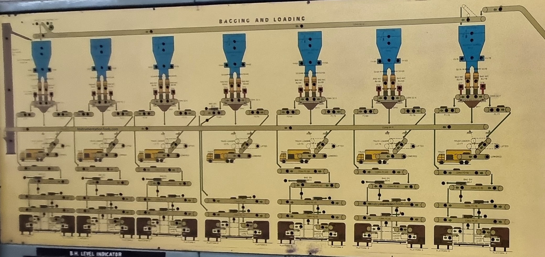
Urea Bagging Plant Process Flow
Urea Bagging Plant Process Flow is as described Below. During the Urea Bagging Process, we have two sections, as follows.
- We want to bag Urea continuously.
- We want to store Urea in Urea Storage Silo.
Urea Direct Bagging
We receive Urea from the Urea Plant via a Material conveyor named MT-1. Material Conveyor dump material on BC-03 and BC-03 Dump material on Flapper gate, Flapper gate navigate the Urea to Bulk Conveyor BC-07.Now BC-07 conveys the Urea to Bulk Conveyor BC-08, BC-08 has a Travelling Tripper (TR) assembly which helps to fill the Urea in the Desired Buffer Hopper (BH).
After filling the required minimum level in Buffer Hopper we can start the Bagging. The minimum Hopper Level for Bagging is 20 % and the Maximum Level is 90 %. After the Bagging and swinging of Urea bags, these bags travel towards their loading point i.e. Wagon loading point and Truck loading point.
Each Buffer hopper has a minimum of two bagging machines and these bagging machines have both sides Flat Conveyor, One for Wagon loading and another for Truck loading.
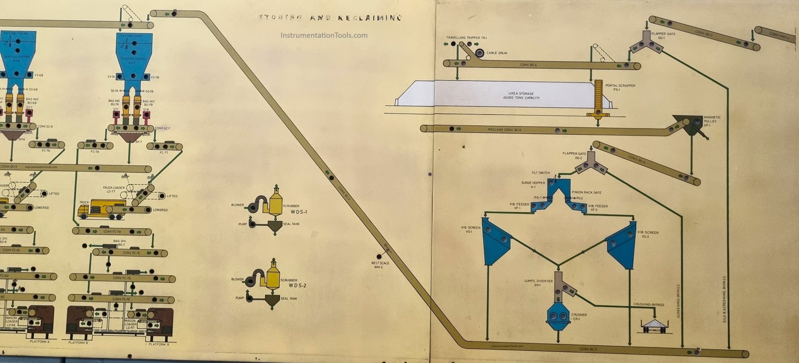
Urea stored in a silo, reclaimed, and then Bagged
We receive the material from Urea Plant via Material Conveyor MT-01 and MT-01 dump material on Bulk Conveyor BC-03 and BC-03 dump material on Flapper gate and Flapper gate dump material on Bulk Conveyor BC-04, BC-04 have Travelling Tripper assembly. Now Urea is stored in the Urea Storage Silo.
During the Urea reclaiming process, Urea is being transferred on Bulk Conveyor BC-05 via Portal Scrapper. BC-05 dumps the material on Bulk Conveyor BC-06 after passing Urea through Magnetic Pulley. Now here we have two choices either we can directly send the claimed Urea to BC-07 or we can send it to BC-07 after the screening process.
During physical observation, if Urea is ok for Bagging then we send it to Bc-07, But if Urea has a lot of dust and Lumps then we have to send it through the standard screening process. In case of defected Urea Flapper gate send it to the Surge hopper.
The Surge hopper has a vibrator feeder assembly that navigates Urea to Vibrator Screening, and the Vibrator Screener Segregates Dust and breaks a few lumps. After this Urea is sent to the Lump diverter, If now Urea is free from Lumps then it is sent to BC-07. Urea lumps are sent to the Crusher Unit and after Crushing Urea is sent to BC-07.
Now all other processes will be the same as Urea Direct Bagging.
Conclusion
After all the above steps we can say that The urea bagging plant plays a crucial role in the efficient packaging and distribution of urea. In short, we can say that the urea bagging plant is essential for maintaining product quality, minimizing environmental impact, and ensuring efficient distribution of this vital fertilizer.