Protection relays are a very important part of electrical systems. They mostly play the role to prevent the circuits from overcurrent. Overcurrent causes a lot of problems due to thermal heating, which damages the components quickly. And as the loads cannot withstand higher current than it’s rating, the internal circuits are damaged over time or even instantaneously. So, protection relays are required in the electrical panel. Apart from overcurrent, protection relays are also categorised to protect from earth fault, abnormal voltage, or issues related to distance which can cause differential issues in transformers or other heavy voltage loads. In overcurrent, the four most used common types of protection relays are 50, 50N, 51, and 51N. In this post, we will understand these types of protection relays.
Is a protection relay required in all the electrical panels?
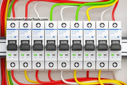
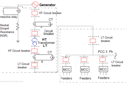
If we think that overcurrent can occur any time and damage the electrical circuit, then theoretically yes; the relay will be required in all the panels. But practically, it is not the case. They are required in panels where a large amount of current flows normally (typically in combination with circuit breakers), as for smaller amounts of current, a normal breaker will do the job. Circuit breakers have certain limitations when used for higher currents, like not sensing abnormal currents, not setting precise time-current curves, or no directional protection, which occur usually as the current increases. So, protection relays are mostly required in MV (medium voltage) and HV (high voltage panels) where it’s combination with the breaker will prevent overcurrent (because a relay can just detect and give a signal, but cannot trip the circuit, which requires the mechanical action of breaker to do the job).
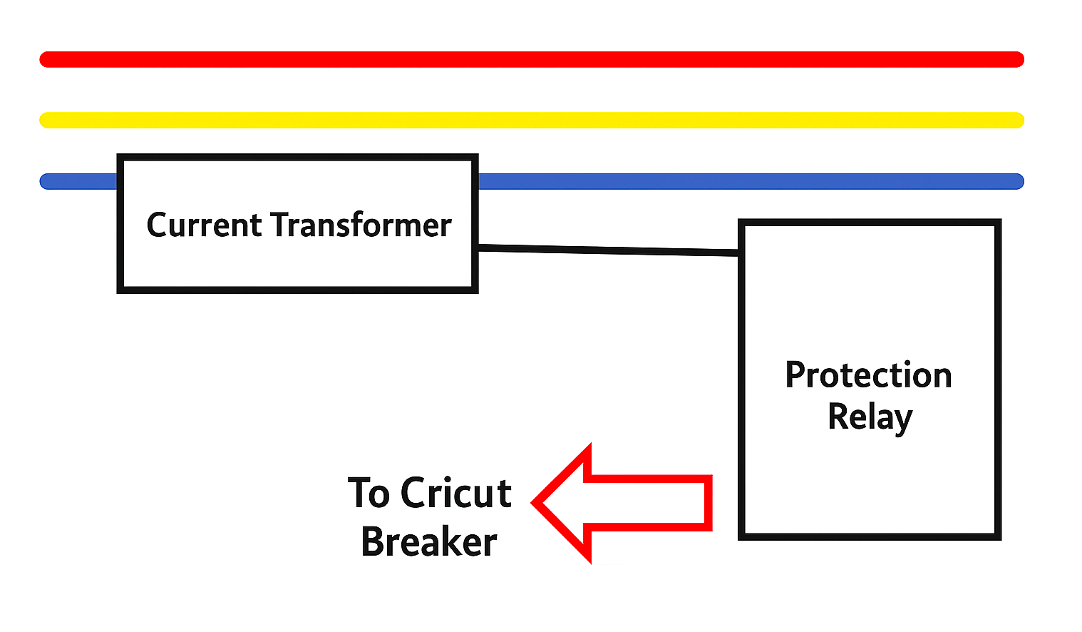
The most important thing to note is that protection relays are always powered by a current transformer’s secondary winding, which is of a low current value. You cannot directly feed primary incomer current (which is huge) to the relay.
Instantaneous overcurrent relay (50)
Now, let us see the first type of overcurrent relay – 50. 50 is the ANSI device number, which is denoted for instantaneous overcurrent. This relay has a fixed and a very minute time delay (typically around less than 0.1 seconds) for sensing overcurrent in the circuit. As soon as it is sensed, the relay will trip the breaker or send a signal to some external controller instantaneously. For this reason, a 50 relay is used when the application is very critical and requires an instant trip in the case of overcurrent due to short circuit or any other related reason. This depends when you know that such current spikes are rare and do not occur in the system frequently. In that case, a sudden spike will cause overcurrent and will thus require immediate tripping. A 50 relay is thus designed for phase overcurrent, will be required to be installed separately for each phase, and detects phase-to-phase overcurrent or phase-to-neutral overcurrent.
Instantaneous earth fault (neutral) overcurrent relay (50N)
Now, this relay is an inverse function of a 50 relay. Instead of phase-to-phase overcurrent or phase-to-neutral overcurrent, the relay will detect leakage current on the neutral or earth line. If it rises above a very high level (trip level), the relay will trip the breaker instantaneously. Similar to a 50 relay, 50N too has a fixed time interval for detecting fault current in the ground or neutral conductor. Leakage is basically a residual current flowing from any of the three phases or the neutral, via the ground path safely to the earth pit. If this residual current is detected to be above the threshold limits of the relay, then too is overcurrent and will trip the breaker connected with the relay. A 50N Relay is thus designed for earth leakage overcurrent, will be required to be installed in the neutral / summation of the three phases, and detects phase to earth overcurrent.
Inverse time overcurrent relay (51)
51 is the ANSI device number, which is denoted for inverse time overcurrent. This is a little complex type of relay to understand, but very useful and dynamic. Instead of tripping instantaneously, the 51 relay works in a variable time manner or inverse time. That means, if the phase-to-phase or phase-to-neutral current is high, then the relay will trip the breaker quickly. And if this current is low (but still above trip level), then the relay will take some time to trip the breaker. So, a 51 relay works on a trip current range, from minimum trip current to maximum trip current. As the current varies, the time delay to check it varies. Such functioning allows a flexible model to work and removes any possibility of false spike to trip the breaker. The three types of time curve types are – standard inverse, very inverse and extremely inverse.
Inverse time earth fault (neutral) overcurrent relay (51N)
It is the same concept as 50N, except that a time curve is followed here according to the 51 standard. That means, if the phase to earth current is high, then the relay will trip the breaker quickly. And if this current is low (but still above trip level), then the relay will take some time to trip the breaker. 51N too follows the three types of time graphs mentioned in the 51 concept.
Read Next:
- What are Switchgear Interlocks?
- What is an Automatic Circuit Recloser?
- What is the LBB Protection Relay?
- Difference Between AIS and GIS Panel
- High-Voltage Testing in Electrical Panels