Inst ToolsInst ToolsInst Tools
  • Courses
  • Automation
    • PLC
    • Control System
    • Safety System
    • Communication
    • Fire & Gas System
  • Instrumentation
    • Design
    • Pressure
    • Temperature
    • Flow
    • Level
    • Vibration
    • Analyzer
    • Control Valve
    • Switch
    • Calibration
    • Erection & Commissioning
  • Interview
    • Instrumentation
    • Electrical
    • Electronics
    • Practical
  • Q&A
    • Instrumentation
    • Control System
    • Electrical
    • Electronics
    • Analog Electronics
    • Digital Electronics
    • Power Electronics
    • Microprocessor
  • Request
Search
  • Books
  • Software
  • Projects
  • Process
  • Tools
  • Basics
  • Formula
  • Power Plant
  • Root Cause Analysis
  • Electrical Basics
  • Animation
  • Standards
  • 4-20 mA Course
  • Siemens PLC Course
Reading: Two-Liquid Manometer Principle
Share
Font ResizerAa
Inst ToolsInst Tools
Font ResizerAa
  • Courses
  • Design
  • PLC
  • Interview
  • Control System
Search
  • Courses
  • Automation
    • PLC
    • Control System
    • Safety System
    • Communication
    • Fire & Gas System
  • Instrumentation
    • Design
    • Pressure
    • Temperature
    • Flow
    • Level
    • Vibration
    • Analyzer
    • Control Valve
    • Switch
    • Calibration
    • Erection & Commissioning
  • Interview
    • Instrumentation
    • Electrical
    • Electronics
    • Practical
  • Q&A
    • Instrumentation
    • Control System
    • Electrical
    • Electronics
    • Analog Electronics
    • Digital Electronics
    • Power Electronics
    • Microprocessor
  • Request
Follow US
All rights reserved. Reproduction in whole or in part without written permission is prohibited.
Inst Tools > Blog > Pressure Measurement > Two-Liquid Manometer Principle

Two-Liquid Manometer Principle

Last updated: March 11, 2019 10:45 am
Editorial Staff
Pressure Measurement
No Comments
Share
1 Min Read
SHARE

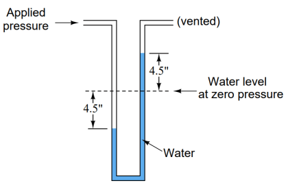
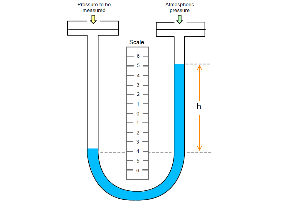
The two-liquid manometer is used to measure very small pressures. This is because a very small applied pressure, will produce a large liquid movement.

The basic arrangement is shown in figure. The manometer consists of two wells, each of the same large cross sectional area, connected by a U-Tube of much smaller cross sectional area.

Two-Liquid Manometer Principle

The U-Tube contains two liquids, one is more densed than the other.

The lower liquid, of density ρ2 is denser than the upper liquid, of density ρ1.

Points to note;

  • The two liquids should be non-mixing and the interface should be clearly visible.
  • The closer the densities of the liquids the more sensitive the manometer.

The scale is usually calibrated by the manufacturer in units of pressure, e.g. mmHg or Pascal, so that the pressure can be read directly from the device.

Don't Miss Our Updates
Be the first to get exclusive content straight to your email.
We promise not to spam you. You can unsubscribe at any time.
Invalid email address
You've successfully subscribed !

Continue Reading

Difference between Absolute, Gauge and Differential Pressure Transmitters
Pneumatic Pressure Transmitters Principle
Pressure Measurement using Manometer
Purpose of Stop in a Pressure Measuring Instrument
Metal Foil Strain Gauge Principle
Impulse Piping standards for Field instruments
Share This Article
Facebook Whatsapp Whatsapp LinkedIn Copy Link
Share
Leave a Comment

Leave a Reply Cancel reply

Your email address will not be published. Required fields are marked *

Stay Connected

128.3kFollowersLike
69.1kFollowersFollow
210kSubscribersSubscribe
38kFollowersFollow

Categories

Explore More

Types of Bourdon Tube
Pressure Unit Conversion Practical Example
Pressure and Temperature Gauges
What are Pressure Sensing Lines? – Causes of Errors in Measurement
Basics of Pressure Measurement
Differential Pressure Gauge Principle
All About Instrumentation Impulse Lines
What is Static Pressure Limit in DP Transmitter ?

Keep Learning

Magnehelic Gauge Calibration

Magnehelic Gauge Calibration

Differential Pressure Sensor for Filtration Monitoring

Differential Pressure Sensor for Filtration Monitoring

Pressure Switch Construction

Basics of Pressure switches

Pressure Sensor Specifications

Pressure Sensor Specifications

Diaphragm Seal Material Selection

Diaphragm Seal Material Selection

Pressure Gauge Accessories

Pressure Gauge Accessories

Pressure Measurement

How to Measure Pressure in Inches of Water Column

inductance transducer

Inductance Type Pressure Transducers Principle

Learn More

Power Systems Questions & Answers

Power Systems MCQ Series 13

Vortex Flow GIF

Working Principle of Vortex Flow Meter

Major issues for Sensors Selection

Major issues for Sensors Selection

explosion-proof electrical enclosures

Classified Areas and Electrical Safety Measures

vibration probe mounting

Mechanical Vibration Switch Principle

4-20mA Loop Power Supply Questions

4-20mA Loop Power Supply Questions and Answers

Process Plant Risk and Safety Management

Safety Roles & Responsibilities of Process Engineering (Detail Design)

Jog button in Motor Start Stop Logic using PLC

Jog Function in Motor Start Stop Logic using PLC

Menu

  • About
  • Privacy Policy
  • Copyright

Quick Links

  • Learn PLC
  • Helping Hand
  • Part Time Job

YouTube Subscribe

Follow US
All rights reserved. Reproduction in whole or in part without written permission is prohibited.
Welcome Back!

Sign in to your account

Username or Email Address
Password

Lost your password?