Inst ToolsInst ToolsInst Tools
  • Courses
  • Automation
    • PLC
    • Control System
    • Safety System
    • Communication
    • Fire & Gas System
  • Instrumentation
    • Design
    • Pressure
    • Temperature
    • Flow
    • Level
    • Vibration
    • Analyzer
    • Control Valve
    • Switch
    • Calibration
    • Erection & Commissioning
  • Interview
    • Instrumentation
    • Electrical
    • Electronics
    • Practical
  • Q&A
    • Instrumentation
    • Control System
    • Electrical
    • Electronics
    • Analog Electronics
    • Digital Electronics
    • Power Electronics
    • Microprocessor
  • Request
Search
  • Books
  • Software
  • Projects
  • Process
  • Tools
  • Basics
  • Formula
  • Power Plant
  • Root Cause Analysis
  • Electrical Basics
  • Animation
  • Standards
  • 4-20 mA Course
  • Siemens PLC Course
Reading: Transistor Emitter Feedback Bias
Share
Font ResizerAa
Inst ToolsInst Tools
Font ResizerAa
  • Courses
  • Design
  • PLC
  • Interview
  • Control System
Search
  • Courses
  • Automation
    • PLC
    • Control System
    • Safety System
    • Communication
    • Fire & Gas System
  • Instrumentation
    • Design
    • Pressure
    • Temperature
    • Flow
    • Level
    • Vibration
    • Analyzer
    • Control Valve
    • Switch
    • Calibration
    • Erection & Commissioning
  • Interview
    • Instrumentation
    • Electrical
    • Electronics
    • Practical
  • Q&A
    • Instrumentation
    • Control System
    • Electrical
    • Electronics
    • Analog Electronics
    • Digital Electronics
    • Power Electronics
    • Microprocessor
  • Request
Follow US
All rights reserved. Reproduction in whole or in part without written permission is prohibited.
Inst Tools > Blog > Electronic Devices & Circuits > Transistor Emitter Feedback Bias

Transistor Emitter Feedback Bias

Last updated: September 27, 2016 5:57 am
Editorial Staff
Electronic Devices & Circuits
No Comments
Share
1 Min Read
SHARE

If an emitter resistor is added to the base-bias circuit, the result is emitter-feedback bias, as shown in Figure. The idea is to help make base bias more predictable with negative feedback, which negates any attempted change in collector current with an opposing change in base voltage. If the collector current tries to increase, the emitter voltage increases, causing an increase in base voltage because VB = VE + VBE.

Transistor Emitter Feedback Bias

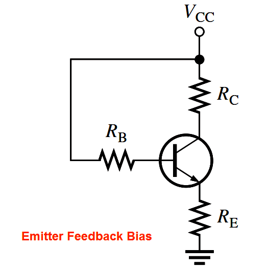
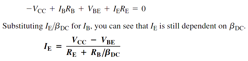
This increase in base voltage reduces the voltage across RB, thus reducing the base current and keeping the collector current from increasing. A similar action occurs if the collector current tries to decrease. While this is better for linear circuits than base bias, it is still dependent on βDC and is not as predictable as voltage-divider bias. To calculate IE, you can write Kirchhoff’s voltage law (KVL) around the base circuit.

Transistor Emitter Feedback Bias Derivation

Don't Miss Our Updates
Be the first to get exclusive content straight to your email.
We promise not to spam you. You can unsubscribe at any time.
Invalid email address
You've successfully subscribed !

Continue Reading

pi filter Operation
Full Wave Rectifier
Transistor Base Bias
Applications of Photo diodes
Diode Limiters/Clippers Operation
Power MOSFET
Share This Article
Facebook Whatsapp Whatsapp LinkedIn Copy Link
Share
Leave a Comment

Leave a Reply Cancel reply

Your email address will not be published. Required fields are marked *

Stay Connected

128.3kFollowersLike
69.1kFollowersFollow
210kSubscribersSubscribe
38kFollowersFollow

Categories

Explore More

Ripple Voltage in Rectifiers
Basic DC Power Supply Circuit
CRT Fluorescent Screen
Forward Bias & Reverse Bias Diode Working Animation
Tunnel Diode Working Principle
Laser Diode Working Principle
Photodiode as Variable Resistance Device
Center Tapped Full Wave Rectifier Operation

Keep Learning

temperature compensation circuit for PMMC

PMMC Temperature Compensation

working-of-pnp-transistor

Working of NPN Transistor

basic-electronics-questions-answers

Basic Electronics Questions & Answers

Transistor-cut-off-saturation-active-regions

Transistor Cut off, Saturation & Active Regions

Transistor Stabilisation

Transistor Stabilisation

Transistor Load Line Analysis

Transistor Load Line Analysis

Open Circuit without Freewheeling diode

Freewheeling Diode Working Principle

Permanent magnet moving coil instruments (PMMC)

Permanent Magnet Moving Coil Instruments (PMMC)

Learn More

non-contact pyrometers distance calculation

Non-contact Pyrometers Characteristics

Mass Flow Calculations of flow measurement

Mass Flow Calculations

wash column temperature control

Pneumatic Instrumentation

Database in Siemens PLC

Steps to Configure TCP/IP Communication in Siemens S7-1200 PLC

Difference between PLC and HMI

Difference between PLC and HMI

Fence grounding specifications

All About Electric Fence Gates

What is a Core Type Transformer

Difference Between Core and Shell Transformers

Lamp Counter Logic

Function Block (FB) for Motor Control Logic

Menu

  • About
  • Privacy Policy
  • Copyright

Quick Links

  • Learn PLC
  • Helping Hand
  • Part Time Job

YouTube Subscribe

Follow US
All rights reserved. Reproduction in whole or in part without written permission is prohibited.
Welcome Back!

Sign in to your account

Username or Email Address
Password

Lost your password?