Inst ToolsInst ToolsInst Tools
  • Courses
  • Automation
    • PLC
    • Control System
    • Safety System
    • Communication
    • Fire & Gas System
  • Instrumentation
    • Design
    • Pressure
    • Temperature
    • Flow
    • Level
    • Vibration
    • Analyzer
    • Control Valve
    • Switch
    • Calibration
    • Erection & Commissioning
  • Interview
    • Instrumentation
    • Electrical
    • Electronics
    • Practical
  • Q&A
    • Instrumentation
    • Control System
    • Electrical
    • Electronics
    • Analog Electronics
    • Digital Electronics
    • Power Electronics
    • Microprocessor
  • Request
Search
  • Books
  • Software
  • Projects
  • Process
  • Tools
  • Basics
  • Formula
  • Power Plant
  • Root Cause Analysis
  • Electrical Basics
  • Animation
  • Standards
  • 4-20 mA Course
  • Siemens PLC Course
Reading: Transistor Base Bias
Share
Font ResizerAa
Inst ToolsInst Tools
Font ResizerAa
  • Courses
  • Design
  • PLC
  • Interview
  • Control System
Search
  • Courses
  • Automation
    • PLC
    • Control System
    • Safety System
    • Communication
    • Fire & Gas System
  • Instrumentation
    • Design
    • Pressure
    • Temperature
    • Flow
    • Level
    • Vibration
    • Analyzer
    • Control Valve
    • Switch
    • Calibration
    • Erection & Commissioning
  • Interview
    • Instrumentation
    • Electrical
    • Electronics
    • Practical
  • Q&A
    • Instrumentation
    • Control System
    • Electrical
    • Electronics
    • Analog Electronics
    • Digital Electronics
    • Power Electronics
    • Microprocessor
  • Request
Follow US
All rights reserved. Reproduction in whole or in part without written permission is prohibited.
Inst Tools > Blog > Electronic Devices & Circuits > Transistor Base Bias

Transistor Base Bias

Last updated: September 27, 2016 7:04 am
Editorial Staff
Electronic Devices & Circuits
No Comments
Share
1 Min Read
SHARE

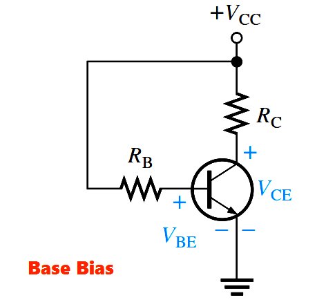
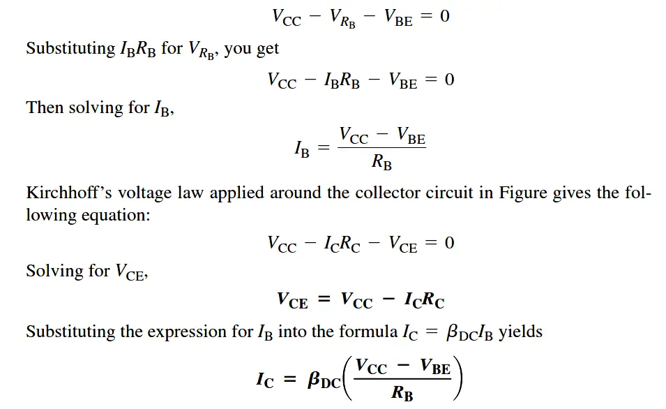
This method of biasing is common in switching circuits. Figure shows a base-biased transistor. The analysis of this circuit for the linear region shows that it is directly dependent on βDC. Starting with Kirchhoff’s voltage law around the base circuit,

transistor-base-bias

transistor-base-bias-derivation


Q-Point Stability of Base Bias

Notice that Above Equation shows that IC is dependent on βDC. The disadvantage of this is that a variation in βDC causes IC and, as a result, VCE to change, thus changing the Q-point of the transistor. This makes the base bias circuit extremely beta-dependent and unpredictable.

Recall that βDC varies with temperature and collector current. In addition, there is a large spread of βDC values from one transistor to another of the same type due to manufacturing variations. For these reasons, base bias is rarely used in linear circuits but is discussed here so you will be familiar with it.

Don't Miss Our Updates
Be the first to get exclusive content straight to your email.
We promise not to spam you. You can unsubscribe at any time.
Invalid email address
You've successfully subscribed !

Continue Reading

Semiconductors Diodes Questions & Answers
Combining Independent Current Sources in Parallel
What is Kirchhoff’s Current Law
Comparison of MOSFET and BJT
Different Types of Diodes
Dependent Voltage Source
Share This Article
Facebook Whatsapp Whatsapp LinkedIn Copy Link
Share
Leave a Comment

Leave a Reply Cancel reply

Your email address will not be published. Required fields are marked *

Stay Connected

128.3kFollowersLike
69.1kFollowersFollow
210kSubscribersSubscribe
38kFollowersFollow

Categories

Explore More

Series and Parallel Resistors
Insulators, Conductors and Semiconductors
Operation of Zener Diode Voltage Regulator
Electronic Symbols
Difference between Schottky Diode and PN junction Diode
How to Test a Diode using Multimeter
Basic DC Power Supply Circuit
Power MOSFET

Keep Learning

Shockley Diode Working Principle

Shockley Diode Working Principle

Comparison of Half wave Rectifiers and Full wave Rectifiers

Comparison of Half wave Rectifiers and Full wave Rectifiers

temperature compensation circuit for PMMC

PMMC Temperature Compensation

What is a Filter Circuit

What is a Filter Circuit ?

Choke Input Filter Operation

Choke Input Filter Operation

pn-junction-energy-diagrams

Energy Diagrams of PN Junction & Depletion Region

seven-segment-display-circuit

Seven Segment Display Working Principle

diode-clamper-circuit

Full Wave Voltage Doubler using Diodes

Learn More

Chemical Sensors Objective Questions

Chemical Sensors Objective Questions

Pictorial Fluid Power Diagram

Hydraulic and Pneumatic P&ID Diagrams and Schematics

wash column temperature control

Pneumatic Instrumentation

Strain Gauge Bridge Circuit

Something is Wrong with Strain Gauge Bridge Circuit

Common Questions on Oil and Natural Gas Industry

Common Questions on Oil and Natural Gas Industry

Ultrasonic Flow Meters Working Principle

Ultrasonic Flow Meters Working Principle

Sensor Based Projects List - Electronics & Electrical

350+ Sensor-Based Projects List – Electronics & Electrical

Free Download Industrial Control System Book

Free Download Industrial Control System Book

Menu

  • About
  • Privacy Policy
  • Copyright

Quick Links

  • Learn PLC
  • Helping Hand
  • Part Time Job

YouTube Subscribe

Follow US
All rights reserved. Reproduction in whole or in part without written permission is prohibited.
Welcome Back!

Sign in to your account

Username or Email Address
Password

Lost your password?