The below Fig. shows the common emitter npn amplifier circuit. Note that a battery VBB is connected in the input circuit in addition to the signal voltage. This d.c. voltage is known as bias voltage and its magnitude is such that it always keeps the emitter-base junction forward *biased regardless of the polarity of the signal source.
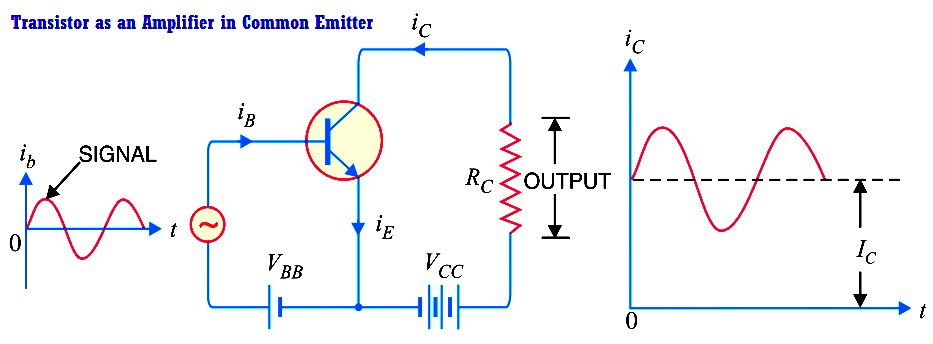
Operation. During the positive half-cycle of the signal, the forward bias across the emitter-base junction is increased. Therefore, more electrons flow from the emitter to the collector via the base. This causes an increase in collector current. The increased collector current produces a greater voltage drop across the collector load resistance RC. However, during the negative half-cycle of the signal, the forward bias across emitter-base junction is decreased. Therefore, collector current decreases. This results in the decreased output voltage (in the opposite direction). Hence, an amplified output is obtained across the load.
Analysis of collector currents. When no signal is applied, the input circuit is forward biased by the battery VBB. Therefore, a d.c. collector current IC flows in the collector circuit. This is called zero signal collector current. When the signal voltage is applied, the forward bias on the emitter-base junction increases or decreases depending upon whether the signal is positive or negative. During the positive half-cycle of the signal, the forward bias on emitter-base junction is increased, causing total collector current iC to increase. Reverse will happen for the negative half-cycle of the signal.
Above Fig. (right) shows the graph of total collector current iC versus time. From the graph, it is clear that total collector current consists of two components, namely ;
(i) The d.c. collector current IC (zero signal collector current) due to bias battery VBB. This is the current that flows in the collector in the absence of signal.
(ii) The a.c. collector current ic due to signal. Total collector current, iC = ic + IC
The useful output is the voltage drop across collector load RC due to the a.c. component ic. The purpose of zero signal collector current is to ensure that the emitter-base junction is forward biased at all times.
Learn an example PLC program to control a pump based on level sensors using ladder…
In the PLC timer application for security camera recording, when motion is detected then camera…
In this example, we will learn batch mixing with PLC ladder logic program using timer…
This PLC example on manufacturing line assembly is an intermediate-level PLC program prepared for the…
In this article, you will learn the PLC programming example with pushbutton and motor control…
This article teaches how to convert Boolean logic to PLC programming ladder logic with the…

View Comments
It is very useful to me, the points guided by you is good. Thank you