Inst ToolsInst ToolsInst Tools
  • Courses
  • Automation
    • PLC
    • Control System
    • Safety System
    • Communication
    • Fire & Gas System
  • Instrumentation
    • Design
    • Pressure
    • Temperature
    • Flow
    • Level
    • Vibration
    • Analyzer
    • Control Valve
    • Switch
    • Calibration
    • Erection & Commissioning
  • Interview
    • Instrumentation
    • Electrical
    • Electronics
    • Practical
  • Q&A
    • Instrumentation
    • Control System
    • Electrical
    • Electronics
    • Analog Electronics
    • Digital Electronics
    • Power Electronics
    • Microprocessor
  • Request
Search
  • Books
  • Software
  • Projects
  • Process
  • Tools
  • Basics
  • Formula
  • Power Plant
  • Root Cause Analysis
  • Electrical Basics
  • Animation
  • Standards
  • 4-20 mA Course
  • Siemens PLC Course
Reading: Functional Block Diagram PLC Example for Traffic Light System
Share
Font ResizerAa
Inst ToolsInst Tools
Font ResizerAa
  • Courses
  • Design
  • PLC
  • Interview
  • Control System
Search
  • Courses
  • Automation
    • PLC
    • Control System
    • Safety System
    • Communication
    • Fire & Gas System
  • Instrumentation
    • Design
    • Pressure
    • Temperature
    • Flow
    • Level
    • Vibration
    • Analyzer
    • Control Valve
    • Switch
    • Calibration
    • Erection & Commissioning
  • Interview
    • Instrumentation
    • Electrical
    • Electronics
    • Practical
  • Q&A
    • Instrumentation
    • Control System
    • Electrical
    • Electronics
    • Analog Electronics
    • Digital Electronics
    • Power Electronics
    • Microprocessor
  • Request
Follow US
All rights reserved. Reproduction in whole or in part without written permission is prohibited.
Inst Tools > Blog > PLC Tutorials > Functional Block Diagram PLC Example for Traffic Light System

Functional Block Diagram PLC Example for Traffic Light System

Learn about the traffic light system in PLC programming using a functional block diagram (FBD) with this example program.

Last updated: October 7, 2024 11:34 am
Viral Nagda
PLC Tutorials
1 Comment
Share
5 Min Read
SHARE

In PLC programming, as there are five programming languages, one of the most preferred and best ones out of them is a functional block diagram. Due to it’s block diagram representation, troubleshooting and viewing becomes very easy.

Contents
Traffic Light SystemFunctional Block Diagram PLC Example

Traffic Light System

One of the most common pieces of logic that every newcomer faces in his career is traffic light signal logic. The logic is taught to new PLC programmers as it uses a good amount of logic, and is not that simple. In this post, we will see traffic light logic in a functional block diagram.

First, let us see the test bench criteria and condition of the logic. As soon as the start button is pressed, the red light will turn on first for a set time of 10 seconds. After that time, the red light will turn off and the yellow light will turn on for a set time of 10 seconds.

After that time, the yellow light will turn off and the green light will turn on for a set time of 10 seconds. After that time, the green light will turn off and the red light will turn on again for a set time of 10 seconds.

The cycle repeats as long as the stop button is not pressed. If in any sequence, the stop button is pressed, then the whole logic will reset and all lamps will turn off. The cycle will start again from scratch once the start button is pressed again.

Functional Block Diagram PLC Example

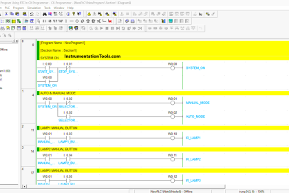
Now that we have seen the question, let us come up with an answer using a functional block diagram. Refer to the below image for the logic written.

We have used two inputs – start and stop push buttons, three outputs – red, yellow, and green lamps, three timers – on timer for each lamp, and one internal variable – showing logic running or not.

Functional Block Diagram PLC Example for Traffic Light System

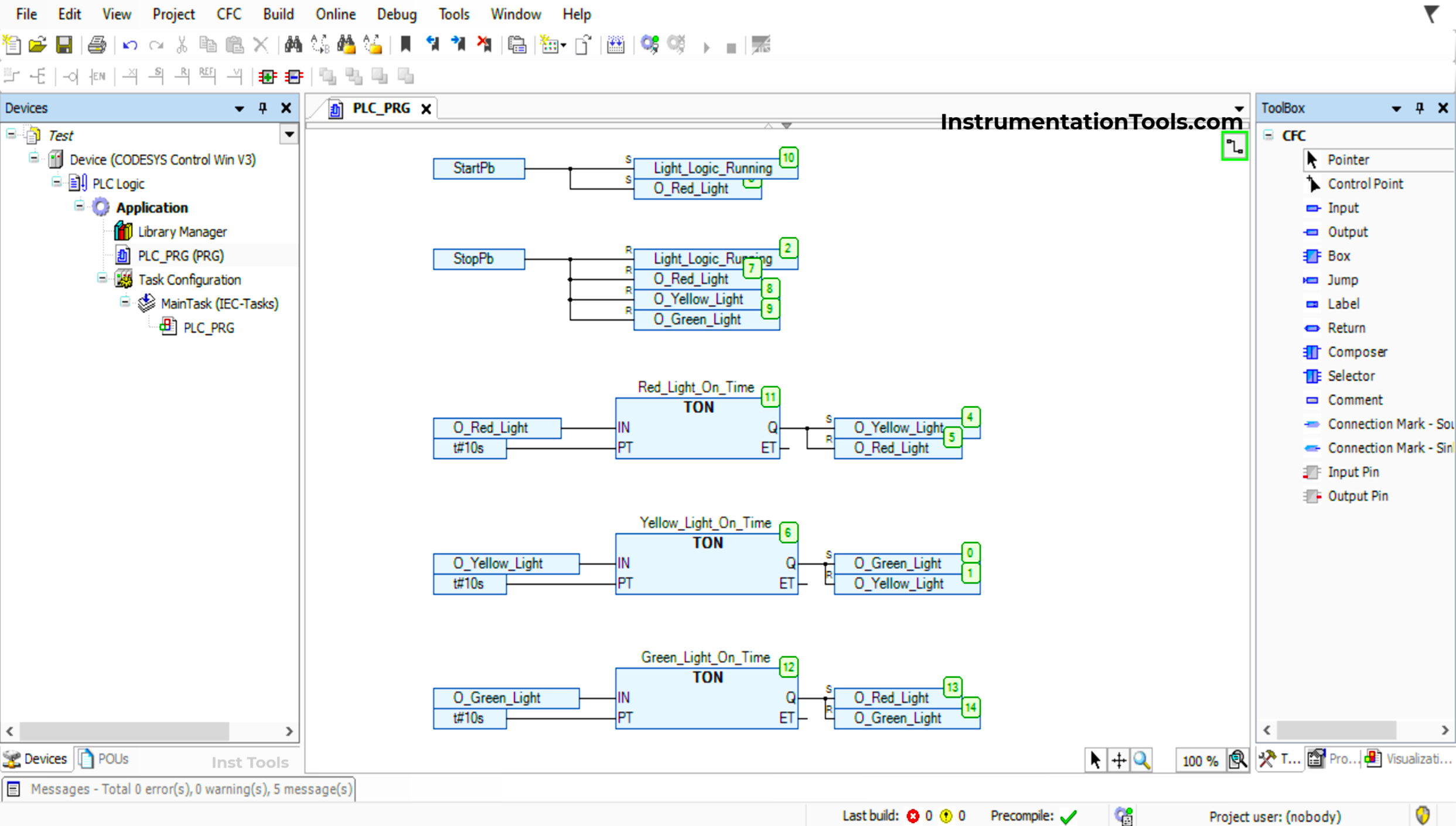
Now, let us start developing the logic. As per the first condition, when we press start, the red light turns on for a set time. So, we have set the light as shown with the S symbol in the image. At the same time, we set the internal variable of the running bit.

Now, we use the red lamp to turn on the red lamp timer for 10 seconds. The output bit of the timer is used to set the yellow lamp first and then reset the red lamp, shown as the R symbol. After this, the red lamp timer turns off.

Now, we use the yellow lamp to turn on the yellow lamp timer for 10 seconds. The output bit of the timer is used to set the green lamp first and then reset the yellow lamp. After this, the yellow lamp timer turns off.

Now, we use the green lamp to turn on the green lamp timer for 10 seconds. The output bit of the timer is used to set the red lamp first and then reset the green lamp. After this, the green lamp timer turns off and the cycle repeats.

We set the bit first, because if we reset first, then the timer too will turn off and the next bit will not set due to PLC scan time. So, in any logic, if we want to continue something, then first start the next one and then stop the preceding one.

As per the last condition of the question, by pressing the stop button, everything should reset. So, on this input, we have reset all the bits used in logic, to enable it to restart once again.

In this way, we have seen the traffic light logic using a functional block diagram.

Read Next:

  • Difference Between PLC and CNC Machine
  • Ladder Logic Test Questions and Answers
  • Traffic Light Control using PLC Ladder Logic
  • Traffic Lights Ladder Diagram using Timers
  • PLC based 4 Way Traffic Light Control System
Don't Miss Our Updates
Be the first to get exclusive content straight to your email.
We promise not to spam you. You can unsubscribe at any time.
Invalid email address
You've successfully subscribed !

Continue Reading

Top 5 Advantages of Human-Machine Interface (HMI)
PLC Program for Control Valve Scaling
How to use JUMP Instruction in PLC Ladder Logic?
How to Work with Allen Bradley RsLogix Emulator?
Start the Counting from a Preset Value in PLC
What is Sequential Function Chart (SFC?)
Share This Article
Facebook Whatsapp Whatsapp LinkedIn Copy Link
Share
1 Comment
  • KRISHNA BALI says:
    January 20, 2025 at 3:20 pm

    Good education for training.

    Reply

Leave a Reply Cancel reply

Your email address will not be published. Required fields are marked *

Stay Connected

128.3kFollowersLike
69.1kFollowersFollow
210kSubscribersSubscribe
38kFollowersFollow

Categories

Explore More

Draw a Ladder Logic to switch ON-OFF a Bulb using a Toggle Switch ?
Anti-static Wrist Straps in Industrial Automation
How to Design a Motor Faceplate in Graphics? – SCADA Tutorials
Turbine-Compressor System Architecture
SCADA Engineer Job Responsibilities and Skills
PLC Program with 2 Toggle Switches and 4 Motors
Delta PLC Counter with Comparison
Parking Garage Indicator: PLC Automation System

Keep Learning

Safety Considerations in PLC System Design

Safety Considerations in PLC System Design

Marshalling Panel

What is Marshalling Cabinet?

Configuration of Siemens Scada and PLC

#12 PLC Best Practices – Validate Inputs based on Physical Plausibility

PLC Example on Manufacturing Line Assembly

PLC Example on Manufacturing Line Assembly

PLC Programming Software

What Factors Affect the Choice of PLC Programming Software?

memory types in siemens plc

Memory Structure of Siemens PLC

PLC Technique for IO Mapping

PLC Techniques for I/O Mapping

21 CFR in SCADA and HMI Systems

What is 21 CFR in SCADA and HMI Systems?

Learn More

Induced Draft Cooling Tower

Cooling Tower fan FRP fan blades saves and saves

Capacitor Bank

Poor Power Factor Boosted – Industrial Electrical Problems

PLC Program using Counters

PLC Counters Program

Industry 4.0 Explained

Industry 4.0 Explained – Industrial Internet of Things

Cable screen shall not be grounded

Cable Screen shall not be Grounded at Field Device ?

Ladder Logic for Flow Meter Totalizer

Ladder Logic for Flow Meter Totalizer

Flare KOD

Flare Knockout Drums Working Animation

Hydrogen Sulfide Gas Detector Calibration Procedure

Hydrogen Sulfide Gas Detector Calibration Procedure

Menu

  • About
  • Privacy Policy
  • Copyright

Quick Links

  • Learn PLC
  • Helping Hand
  • Part Time Job

YouTube Subscribe

Follow US
All rights reserved. Reproduction in whole or in part without written permission is prohibited.
Welcome Back!

Sign in to your account

Username or Email Address
Password

Lost your password?