Totally Enclosed Fan Cooled (TEFC) motors are rampant and frequent winding burnouts need immediate stopping.
The infructuous enormous maintenance expenses and repetitive tasks depressed the plant personnel, especially operating and electrical morale.
Note: This root cause analysis (RCA) is from real-time scenarios that happened in industries during the tenure of one or two decades ago. These articles will help you to improve your troubleshooting skills and knowledge.
Totally Enclosed Fan Cooled (TEFC) Motor Essential Information
The finned body motor end covers fitted antifriction bearings support the motor rotor (below figure).
The stator windings distribute around the motor body bore. Keyed to the rotor internal fan circulates housing bottled air within the motor interior.
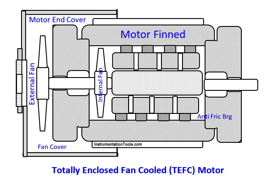
The interior circulating air picks up the rotor and stator winding heat, conducts it to the motor finned casing. This way the ambient corrosives and dusts laden air does not enter inside the motor and affect the internals.
An external fan blown outside air over the motor casing integral fins absorbs the motor losses developed heat and rejects it into the environs.
Thus, the motor winding temps remain well within their temperature ratings; e.g., motor designs aim to hold the common 115 o C rated class B windings temperature.
around 80o C. Remember, the cooler the winding the longer their lives; as winding temp increase exponentially decreases the expected 20-25 years winding lives.
Root Cause Analysis
The problem RCA found causes are:
- The corrosive dust sticks hard to the fins; eventually fills the inter-fin gaps and thwarts the fan blown air cooling
- Consequent rampant and frequent motor winding burnouts reduce the plant availabilities though crew put spare motors quickly, using the author thought out even different frame motor quick changes.
- Touch felt dust-covered motors casing temperatures were worthless.
- Fortnightly plant SD quick cleanups don’t remove the stuck stubborn inter-fins gaps fills
- The thin sheet steel fans and fan covers corrode away within few months, consequent much less blown airflow rates increase the winding temps way high and accelerate the winding burnouts
- HT motors’ visible grease feed pipes reminded the crew grease them as the name plate directs. However, the fan-cover hided NDE 1/8” pipe threaded very small grease nipple the coupling guard covered DE grease nipple. In addition, dust covering hid the already less visible 1/8” NPT DE and NDE grease nipples totally. Hence, the crew and supervisors took LT motor AFBs don’t need regreasing. On the contrary 1500 RPM motors need regreasing 2000 hourly and 3000 RPM motors every 1000 hours. In addition, 3‑yearly motor dissembles, benzene or other solvent washing the AFBs old grease without dissembling from the shaft, and 2/3 volume fresh grease fills are must to realize the AFBs 50000, to 200000 hours L-10 lives. Not doing this besides the other points discussed under AFB failures’ case studies caused frequent AFB change SDs, increased the crews’ workload and reduced the plant availabilities.
Solution & Benefits
Several days thinking resulted solutions are:
- Unscrew the NDE grease fitting immediately, screw in sufficient length 1/8” pipe in their place. The pipe shall protrude 50-mm beyond the fan cover. Screw in the grease fitting on to the pipe. Create similar arrangement for the DE bearing. Grease 3000-RPM both bearings 1000 hourly, pumping the specified quantity grease and 1500-RPM 2000 hourly.
- Dissemble 3000 RPM motors 18‑monthly, remove the old grease collected within the body, save for fasteners threads greasing. Wash out the grease from the bearings with diesel, wipe dry and fill 2/3 the bearing volume new grease. NEVER spin ungreased bearings. Do these tasks 36-monthly for 1500-RPM motors
- Replace the thin corrosion prone sheet steel cooling fans and fan covers with 8‑mm thick never corroding FRP (fiber-reinforced plastics) items. A local FRP vendor made the fans and fan covers using the damaged items as models and his imagination of what the undamaged items would look and what the various sizes would be and getting constant clarifications from an assigned electrical engineer (EE); the EE consulted the author when needed. Secure these with up to 6‑mm SS screws and larger dia carbon steel screws both greased well. These last and last, do not rust; hence easily screw in / screw out.
- The motor vendor never supplying these ordered spares problem too vanishes – a bonus advantage
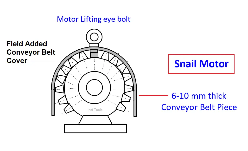
- Take the efforts and time for onetime inter-fin fills clean out. Immediately, cover the motor with an 8 to 10 mm thick conveyor belt piece, wide enough to overlap fan cover and shaft coupling approx. 50 mm, and length to cover the motor entirely until the baseplate (fig 11).
- Online hosing effectively shines the cover
- Cover removal for motor dissembles is not necessary. Hence, the cover never separates from the motor, crew cannot forget to put it back and ever stays with the motor. Hence, the crews nicknamed the covered motors ‘Snail Motors’.
- The author ensured the above steps strict compliance till the crew imbibed them as habit and followed
RCA Solution Benefits
RCA solution Benefits are.
- Near extinct motor burnouts achieved at negligible costs and efforts because of:
- Simplest, loss proof, most effective and near zero cost cover
- The cover effectively prevents dust fall on the motor; hence, no dust filled fin-gaps. Thus, vanishes a near impossible recurring cleaning task
- a + b prevent air scatter, confine the airflow along the full fin length, and the high air velocities prevent dust settling in the fin gaps and filling them, i.e., cools the motor better than design and it stays ever!
- In addition, high velocity airflow over bare metal, increases heat transfer coefficients i.e., increases the motor and windings cooling better than design
- Hence, vanished winding burnouts, remarkably boosted on stream hours and production gain
Near zero rewinding and other maintenance costs
Author: S. Raghava Chari
Do you face any similar issues? Share with us through the below comments section.
If you liked this article, then please subscribe to our YouTube Channel for Instrumentation, Electrical, PLC, and SCADA video tutorials.
You can also follow us on Facebook and Twitter to receive daily updates.
Read Next: