A compromise between two-wire and four-wire RTD connections is the three-wire connection, which looks like this:
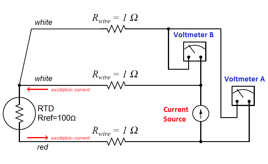
In a three-wire RTD circuit, voltmeter “A” measures the voltage dropped across the RTD plus the voltage dropped across the bottom current-carrying wire. Voltmeter “B” measures just the voltage dropped across the top current-carrying wire. Assuming both current-carrying wires will have (very nearly) the same resistance, subtracting the indication of voltmeter “B” from the indication given by voltmeter “A” yields the voltage dropped across the RTD:
VRTD = Vmeter(A) − Vmeter(B)
Once again, RTD resistance is calculated from the RTD voltage and the known current source value using Ohm’s Law, just as it is in a 4-wire circuit.
If the resistances of the two current-carrying wires are precisely identical (and this includes the electrical resistance of any connections within those current-carrying paths, such as terminal blocks), the calculated RTD voltage will be the same as the true RTD voltage, and no wire-resistance error will appear. If, however, one of those current-carrying wires happens to exhibit more resistance than the other, the calculated RTD voltage will not be the same as the actual RTD voltage, and a measurement error will result.
Thus, we see that the three-wire RTD circuit saves us wire cost over a four-wire circuit, but at the “expense” of a potential measurement error. The beauty of the four-wire design was that wire resistances were completely irrelevant: a true determination of RTD voltage (and therefore RTD resistance) could be made regardless of how much resistance each wire had, or even if the wire resistances were different from each other. The error-canceling property of the three-wire circuit, by contrast, hinges on the assumption that the two current-carrying wires have exactly the same resistance, which may or may not actually be true.
It should be understood that real three-wire RTD instruments do not employ direct-indicating voltmeters as shown in these simplified examples. Actual RTD instruments use either analog or digital “conditioning” circuits to measure the voltage drops and perform the necessary calculations to compensate for wire resistance. The voltmeters shown in the four-wire and three-wire diagrams serve only to illustrate the basic concepts, not to showcase practical instrument designs.
Also Read : RTD Interview Questions
Credits : Tony R. Kuphaldt – Creative Commons Attribution 4.0 License
