So far, our discussion has dealt with the operation of single-phase transformers. Three-phase transformer operation is identical except that three single-phase windings are used. These windings may be connected in wye, delta, or any combination of the two.
In the delta connection, all three phases are connected in series to form a closed loop (Figure 1).
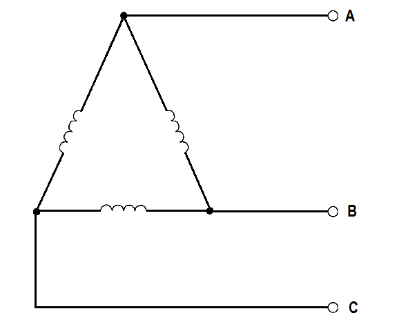
Figure 1 : Delta Connection
In the wye connection, three common ends of each phase are connected together at a common terminal (marked “N” for neutral), and the other three ends are connected to a three-phase line (Figure 2).
Figure 2 : Wye Connection
A three-phase transformer may have three separate but identical single-phase (1φ) transformers or a single 3φ unit containing three-phase windings. The transformer windings may be connected to form a 3φ bank in any of four different ways (Figure 3).
Figure 3 : 3φ Transformer Connections
Figure 3 shows the voltages and currents in terms of applied line voltage (V) and line current (I), where the turns ratio (a) is equal to one. Voltage and current ratings of the individual transformers depend on the connections (Figure 3) and are indicated by below Table for convenience of calculations.
Example 1:
If line voltage is 440 V to a 3φ transformer bank, find the voltage across each primary winding for all four types of transformer connections.
Solution :
Δ – Δ : Primary Voltage = V = 440 Volts
Y – Y : Primary Voltage = V/√3 = 440/1.73 = 254.3 volts
Y – Δ : Primary Voltage = V/√3 = 440/1.73 = 254.3 volts
Δ – Y : Primary Voltage = V = 440 Volts
Example 2:
If line current is 10.4 A in a 3φ transformer connection, find the primary phase current.
Solution :
Δ – Δ : Primary Phase Current = I/√3 = 10.4/1.73 = 6 amps
Y – Y : Primary Phase Current = I = 10.4 amps
Y – Δ : Primary Phase Current = I = 10.4 amps
Δ – Y : Primary Phase Current = I/√3 = 10.4/1.73 = 6 amps
Example 3:
Find the secondary line current and phase current for each type of transformer connection, if primary line current is 20 amps, and the turns ratio is 4:1.
Solution :
∆-∆ : Secondary line current = 4(20) = 80 amps
∆-∆ : Secondary Phase current = aI/√3 = (4×20) / 1.73 = 46.2 amps
Y-Y : Second line current = aI = 4(20) = 80 amps
Y-Y : Second phase current = aI = 4(20) = 80 amps
Y-∆ : Second line current = √3aI = 4(20)(1.73) = 138.4 amps
Y-∆ : Second phase current = aI = 4(20) = 80 amps
∆-Y : Second line current = aI/√3 = (4×20) / 1.73 = 46.2 amps
∆-Y : Second phase current = aI/√3 = (4×20) / 1.73 = 46.2 amps
The conveyor sorting machine is widely used in the packing industries using the PLC program…
Learn the example of flip-flop PLC program for lamps application using the ladder logic to…
In this article, you will learn the STAR DELTA programming using PLC controller to start…
Lube oil consoles of rotary equipment packages in industrial process plants are usually equipped with…
Rotating equipment packages such as pumps, compressors, turbines need the lube oil consoles for their…
This article explains how to blink lights in ladder logic with a detailed explanation video…


