Inst ToolsInst ToolsInst Tools
  • Courses
  • Automation
    • PLC
    • Control System
    • Safety System
    • Communication
    • Fire & Gas System
  • Instrumentation
    • Design
    • Pressure
    • Temperature
    • Flow
    • Level
    • Vibration
    • Analyzer
    • Control Valve
    • Switch
    • Calibration
    • Erection & Commissioning
  • Interview
    • Instrumentation
    • Electrical
    • Electronics
    • Practical
  • Q&A
    • Instrumentation
    • Control System
    • Electrical
    • Electronics
    • Analog Electronics
    • Digital Electronics
    • Power Electronics
    • Microprocessor
  • Request
Search
  • Books
  • Software
  • Projects
  • Process
  • Tools
  • Basics
  • Formula
  • Power Plant
  • Root Cause Analysis
  • Electrical Basics
  • Animation
  • Standards
  • 4-20 mA Course
  • Siemens PLC Course
Reading: Thermostatic Valves Working Principle
Share
Font ResizerAa
Inst ToolsInst Tools
Font ResizerAa
  • Courses
  • Design
  • PLC
  • Interview
  • Control System
Search
  • Courses
  • Automation
    • PLC
    • Control System
    • Safety System
    • Communication
    • Fire & Gas System
  • Instrumentation
    • Design
    • Pressure
    • Temperature
    • Flow
    • Level
    • Vibration
    • Analyzer
    • Control Valve
    • Switch
    • Calibration
    • Erection & Commissioning
  • Interview
    • Instrumentation
    • Electrical
    • Electronics
    • Practical
  • Q&A
    • Instrumentation
    • Control System
    • Electrical
    • Electronics
    • Analog Electronics
    • Digital Electronics
    • Power Electronics
    • Microprocessor
  • Request
Follow US
All rights reserved. Reproduction in whole or in part without written permission is prohibited.
Inst Tools > Blog > Control Valves > Thermostatic Valves Working Principle

Thermostatic Valves Working Principle

Last updated: March 21, 2019 11:11 pm
Editorial Staff
Control Valves
1 Comment
Share
3 Min Read
SHARE

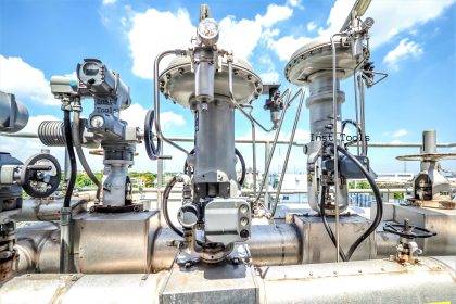
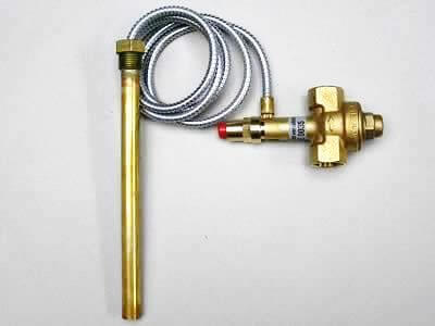
Thermostatic valves are used for the infinite, proportional regulation of flow quantity, depending on the setting and the sensor temperature. The valves are self-acting, i.e. they operate without the supply of auxiliary energy such as electricity or compressed air.

Contents
Thermostatic ValvesHow it Works ?

Thermostatic Valves

Thermostatic valves Principle

Because the valves constantly match flow quantity to demand, they are especially suitable for temperature regulation. The required temperature is maintained constant with no over consumption of:

  • cooling water in cooling systems,
  • hot water or steam in heating systems.

The operating economy and efficiency is maximized.

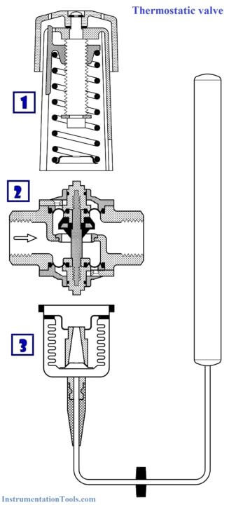
Thermostatic valves consist of three main elements:

1. Setting section with knob, reference spring and setting scale.

2. Valve body with orifice, closing cone and sealing elements.

3. Hermetically sealed thermostatic element with sensor, bellows and charge.

Thermostatic valves Working Principle

How it Works ?

When the three elements are built together, the valve is installed and the sensor is located at the point where the temperature is to be regulated, the function sequence is as follows:

1. A temperature-dependent pressure charge vapour pressure – builds up in the sensor.

2. This pressure is transferred to the valve via the capillary tube and bellows and acts as an opening or closing force.

3. The knob on the setting section and the spring exert a force that acts counter to the bellows.

4. When balance is created between the two opposing forces, the valve spindle remains in its position.

5. If the sensor temperature – or the settings – is changed, the point of balance becomes displaced and the valve spindle moves until balance is re-established, or the valve is fully open or closed.

6. On sensor temperature change, the flow quantity change is approximately proportional.

Thermostatic valves are widely used for temperature regulation in many different machines and installations where cooling is required. Thermostatic valve always opens to admit flow on rising sensor temperature. The valve can be installed either in the cooling water flow line or return line.
Articles You May Like :

HVAC Valves

Control Valve Cv or Kv

Electric Motor Actuator

Questions on Control Valves

Dampers and Louvres

Don't Miss Our Updates
Be the first to get exclusive content straight to your email.
We promise not to spam you. You can unsubscribe at any time.
Invalid email address
You've successfully subscribed !

Continue Reading

What is a Electric Motor Actuator ?
Solenoid Valves Selection Guidelines
Over Pressure cases for Pressure Relief Valve Sizing
How Ball Valves Work ?
Solenoid Valve Failure in Plant Start-Up: Identifying the Root Cause
What is a Float Control Valve? Types, Advantages, Disadvantages
Share This Article
Facebook Whatsapp Whatsapp LinkedIn Copy Link
Share
1 Comment
  • Kansara Urvesh B. says:
    September 15, 2016 at 3:44 am

    Nice tips

    Reply

Leave a Reply Cancel reply

Your email address will not be published. Required fields are marked *

Stay Connected

128.3kFollowersLike
69.1kFollowersFollow
210kSubscribersSubscribe
38kFollowersFollow

Categories

Explore More

What is Shutdown Valve?
Ball Valve Material Selection
Two Solenoid Valves Working Principle
Effect of Differential Pressure on Control Valve Lift
Constant Flow Valve Principle
Basics of Control Valves
Control Valve Working Animation
Snap Acting Relay Working Principle

Keep Learning

Dome Valve Principle

Dome Valve Working Principle

Compare Solenoid Valve Manual reset and Manual Override

Compare Solenoid Valve Manual Reset and Solenoid Manual Override

Choke Valve Hydro Test Setup

Choke Valve Hydro Testing Procedure

cavitation-control valve trim

What is Control Valve Cavitation ?

Trip Valve Shown Tripped

Trip Valve Principle

valve-actuator

Pneumatic Control Valve Actuators

How to Remove Control Valve Stem Packing Procedure

The Replacement Procedure for Control Valve Stem Packing

Classification of valves

Introduction to Types of Valves

Learn More

Physic Homework

Physic Homework Help – Tips to Find Professional Assistance

Types of Tank Gauging Level Measurement Systems

Types of Tank Gauging Level Measurement Systems

Wet Leg Level Transmitter

Basics of DP Level Measurement

Safety interlock for motor starters in Siemens PLC

Motor Starter Logic using Siemens PLC Tia Portal

How to Get a PLC Programming Job With No Experience

How to Get a PLC Programming Job With NO Experience?

Gas Detection System Abbreviations

Gas Detection System Abbreviations

How to Activate the Schneider PLC Software License

How to Download EcoStruxure Machine Expert? Schneider PLC Software

Siemens TIA Portal program blocks

Tia Portal – Optimized and Standard Data Block Access

Menu

  • About
  • Privacy Policy
  • Copyright

Quick Links

  • Learn PLC
  • Helping Hand
  • Part Time Job

YouTube Subscribe

Follow US
All rights reserved. Reproduction in whole or in part without written permission is prohibited.
Welcome Back!

Sign in to your account

Username or Email Address
Password

Lost your password?