Inst ToolsInst ToolsInst Tools
  • Courses
  • Automation
    • PLC
    • Control System
    • Safety System
    • Communication
    • Fire & Gas System
  • Instrumentation
    • Design
    • Pressure
    • Temperature
    • Flow
    • Level
    • Vibration
    • Analyzer
    • Control Valve
    • Switch
    • Calibration
    • Erection & Commissioning
  • Interview
    • Instrumentation
    • Electrical
    • Electronics
    • Practical
  • Q&A
    • Instrumentation
    • Control System
    • Electrical
    • Electronics
    • Analog Electronics
    • Digital Electronics
    • Power Electronics
    • Microprocessor
  • Request
Search
  • Books
  • Software
  • Projects
  • Process
  • Tools
  • Basics
  • Formula
  • Power Plant
  • Root Cause Analysis
  • Electrical Basics
  • Animation
  • Standards
  • 4-20 mA Course
  • Siemens PLC Course
Reading: Thermocouple Software compensation
Share
Font ResizerAa
Inst ToolsInst Tools
Font ResizerAa
  • Courses
  • Design
  • PLC
  • Interview
  • Control System
Search
  • Courses
  • Automation
    • PLC
    • Control System
    • Safety System
    • Communication
    • Fire & Gas System
  • Instrumentation
    • Design
    • Pressure
    • Temperature
    • Flow
    • Level
    • Vibration
    • Analyzer
    • Control Valve
    • Switch
    • Calibration
    • Erection & Commissioning
  • Interview
    • Instrumentation
    • Electrical
    • Electronics
    • Practical
  • Q&A
    • Instrumentation
    • Control System
    • Electrical
    • Electronics
    • Analog Electronics
    • Digital Electronics
    • Power Electronics
    • Microprocessor
  • Request
Follow US
All rights reserved. Reproduction in whole or in part without written permission is prohibited.
Inst Tools > Blog > Temperature Measurement > Thermocouple Software compensation

Thermocouple Software compensation

Last updated: April 20, 2019 5:52 pm
Editorial Staff
Temperature Measurement
1 Comment
Share
3 Min Read
SHARE

Previously, it was suggested that automatic compensation could be accomplished by intentionally inserting a temperature-dependent voltage source in series with the circuit, oriented in such a way as to oppose the reference junction’s voltage:

Thermocouple Software compensation

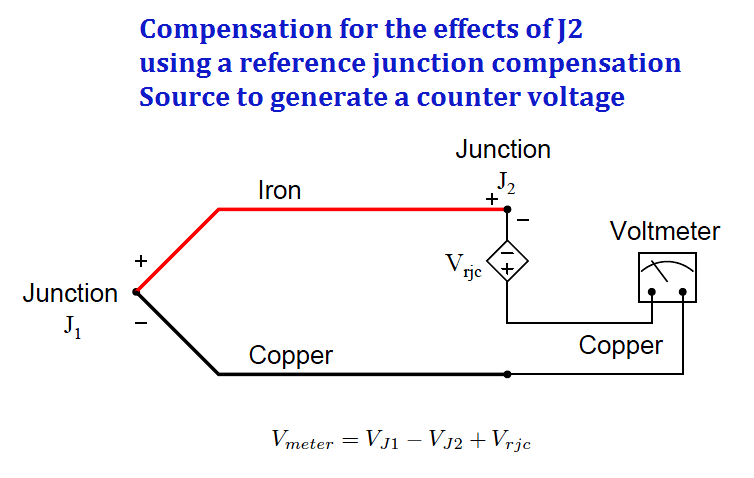
If the series voltage source Vrjc is exactly equal in magnitude to the reference junction’s voltage (VJ2), those two terms cancel out of the equation and lead to the voltmeter measuring only the voltage of the measurement junction J1:

  • Vmeter = VJ1 + 0
  • Vmeter = VJ1

This technique is known as hardware compensation, and is employed in analog thermocouple temperature transmitter designs.

Previously we saw an example of this called an ice point, the purpose of which was to electrically counter the reference junction voltage to render that junction’s voltage inconsequential as though that junction were immersed in a bath of ice-water.

A modern technique for reference junction compensation more suitable to digital transmitter designs is called software compensation:

reference junction compensation

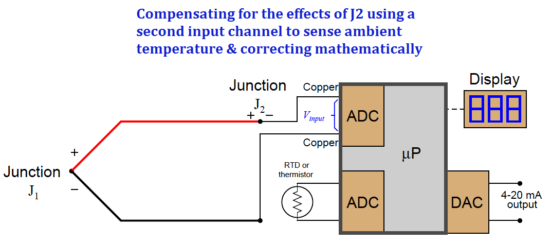
Instead of canceling the effect of the reference junction electrically, we cancel the effect arithmetically inside the microprocessor-based transmitter. In other words, we let the receiving analog-digital converter circuit see the difference in voltage between the measurement and reference junctions (Vinput = VJ1 āˆ’ VJ2), but then after digitizing this voltage measurement we have the microprocessor add the equivalent voltage value corresponding to the ambient temperature sensed by the RTD or thermistor (Vrjc):

  • Compensated total = Vinput + Vrjc
  • Compensated total = (VJ1 āˆ’ VJ2) + Vrjc

Since we know the calculated value of Vrjc should be equal to the real reference junction voltage (VJ2), the result of this digital addition should be a compensated total equal only to the measurement junction voltage VJ1:

  • Compensated total = VJ1 āˆ’ VJ2 + Vrjc
  • Compensated total = VJ1 + 0
  • Compensated total = VJ1

A block diagram of a thermocouple temperature transmitter with software compensation appears here:

SMART Temperature Transmitters

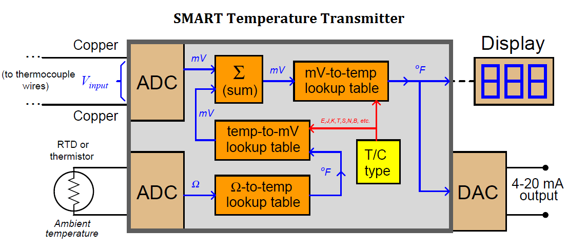
Perhaps the greatest advantage of software compensation is the flexibility to easily switch between different thermocouple types with no hardware modification. So long as the microprocessor memory is programmed with look-up tables relating voltage values to temperature values, it may accurately measure (and compensate for the reference junction of) any thermocouple type.

Hardware-based compensation schemes (e.g. an analog ā€œice pointā€ circuit) require re-wiring or replacement to accommodate different thermocouple types, since each ice-point circuit is built to generate a compensating voltage for a specific type of thermocouple.

Credits : Tony R. Kuphaldt – Creative Commons Attribution 4.0 License

Don't Miss Our Updates
Be the first to get exclusive content straight to your email.
We promise not to spam you. You can unsubscribe at any time.
Invalid email address
You've successfully subscribed !

Continue Reading

Introduction to RTDs
Ambient Temperature Effects on RTD
Temperature Controller Problem
Types of Thermocouples
Difference Between RTD, Thermocouple and Thermistor
Thermistor Working Principle
Share This Article
Facebook Whatsapp Whatsapp LinkedIn Copy Link
Share
1 Comment
  • Simon Watah says:
    March 17, 2021 at 8:49 am

    Very helpful knowledge when trying trying to understand how bimex calibrator is connected and used to do function testing on thermocouple.

    Reply

Leave a Reply Cancel reply

Your email address will not be published. Required fields are marked *

Stay Connected

128.3kFollowersLike
69.1kFollowersFollow
210kSubscribersSubscribe
38kFollowersFollow

Categories

Explore More

Thermocouple and its Principle
Free Download Thermocouple Calculator
Components of RTD
What is a Three-wire RTD ?
RTD Standards
Thermocouples Law of Intermediate Metals
Temperature Sensor Accessories
Filled-bulb Temperature Sensors

Keep Learning

Why have been limits imposed on the frequency ratio for thermowells?

Temperature Sensors Interview Questions

Temperature Sensors Interview Questions

Thermowell Installation near Critical Equipment

Thermowell Installation near Critical Equipment

Temperature Transmitter Foundation Fieldbus Configuration

Foundation Fieldbus Temperature Transmitter Configuration

What to Choose RTD or Thermocouple ?

Thermowell Problems

Thermowell Problems

Temperature Switch Working

Basics of Temperature Switch

Two Wire RTD Lead Wire Resistance Error

Temperature Error of 2-Wire, 3-Wire & 4-Wire RTD

Learn More

Electrical Conductivity Meter

What is the Application of Electrical Conductivity Meter?

Venturi Flow Measurement Principle

Why Flow is Directly Proportional to the Square Root of DP?

Electrical Machines Questions and Answers

Induction Motor Phasor Diagram

Sump Tank Level Transmitter

Problem with Sump Tank Level Transmitter

Current to Voltage Conversion Circuit

How to Convert Current to Voltage using Resistor ?

Configuration of Siemens Scada and PLC

#12 PLC Best Practices – Validate Inputs based on Physical Plausibility

Hydraulic Motor Forward and Reverse Control with Simulation

Hydraulic Motor Forward and Reverse Control with Simulation

PLC Data comparison instructions

PLC Data Comparison Instructions

Menu

  • About
  • Privacy Policy
  • Copyright

Quick Links

  • Learn PLC
  • Helping Hand
  • Part Time Job

YouTube Subscribe

Follow US
All rights reserved. Reproduction in whole or in part without written permission is prohibited.
Welcome Back!

Sign in to your account

Username or Email Address
Password

Lost your password?