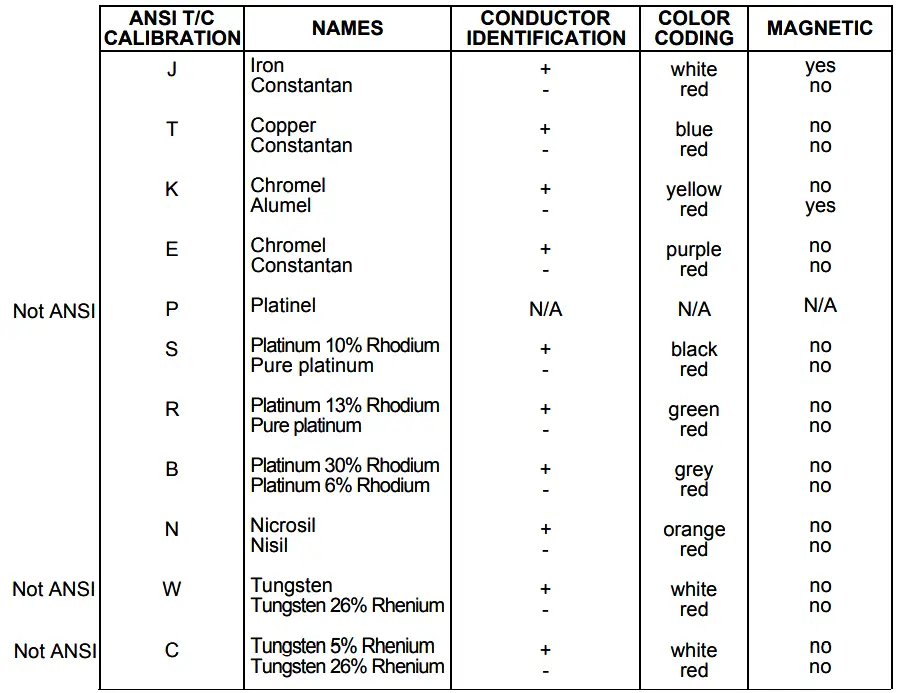
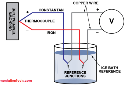
Thermocouple Applications :
(J)–Iron vs Constantan (Most Common)
May be used in vacuum, oxidizing, reducing, and inert atmospheres. Heavier gauge wire is recommended for long term life above 1000°F since the iron element oxidizes rapidly at these temperatures.
(T)–Copper vs Constantan (Most Common Cold)
May be used in vacuum, oxidizing, reducing, and inert atmospheres. It is resistant to corrosion in most atmospheres. High stability at sub-zero temperatures and its limits of error are guaranteed at cryogenic temperatures.
(K)–Chromel vs Alumel (Most Common Real Hot)
Recommended for continuous use in oxidizing or inert atmospheres up to 2300°F (1260°C), especially above 1000°F. Cycling above and below 1800°F (1000°C), is not recommended due to EMF alteration from hysteresis effects. Should not be used in sulfurous or alternating reducing and oxidizing atmospheres unless protected with protection tubes. Fairly reliable and accurate at high temperatures.
(E)–Chromel vs Constantan
May be used in oxidizing or inert atmospheres, but not recommended for alternating oxidizing or inert atmospheres. Not subject to corrosion under most atmospheric conditions. Has the highest EMF produced per degree than any other standard thermocouple and must be protected from sulfurous atmospheres.
(S,R)–Platinum vs Platinum Rhodium (Most Common Real, Real Hot)
Recommended for use in oxidizing or inert atmospheres. Reducing atmospheres may cause excessive grain growth and drifts in calibration.
(N)–Nicrosil vs Nisil (New … Better Than “K”)
May be used in oxidizing, dry reducing, or inert atmospheres. Must be protected in sulfurous atmospheres. Very reliable and accurate at high temperatures. Can replace Type K thermocouples in many application.
(W)–Tungsten vs Rhenium
Recommended for use in vacuum, high purity hydrogen, or pure inert atmospheres. May be used at very high temperatures (2316°C), however, is inherently brittle.
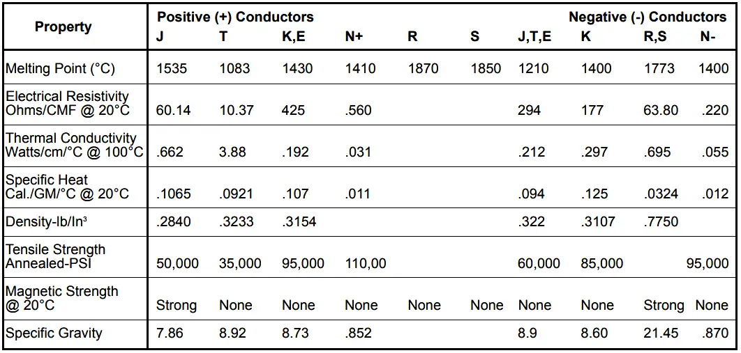
Thermocouple Properties :
TYPE E-The negative wire has lower resistance in ohms per foot than the positive element for the same size wire.
TYPE J-The positive element is frequently rusty and is magnetic. It has a lower resistance in ohms per foot for the same size wire.
TYPE K-The negative element is slightly magnetic. It has a lower resistance in ohms per foot for the same size positive wire.
TYPE R or S-The negative wire is softer. The positive wire has a lower resistance in ohms per foot for the same size wire.
TYPE T-The negative wire is silver in appearance. The positive wire has a lower resistance in ohms per foot for the same size wire, and is usually copper colored.
TYPE N-The positive leg has a higher resistance in ohms per foot for the same size wire.
Note: When in doubt, twist the wire together, and connect opposite ends to a volt meter. Heat the twisted end with a cigarette lighter. If the volts go up – polarity is correct …
Thermocouple Facts
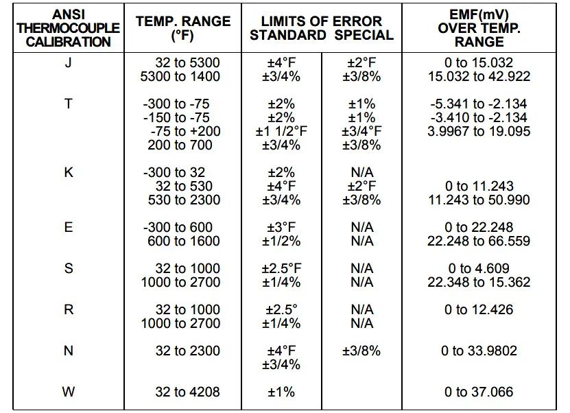
Note: To determine the limits of error in degrees C, multiply the limits of error in degrees F x 5/9.
Thermocouple Element Construction Details :
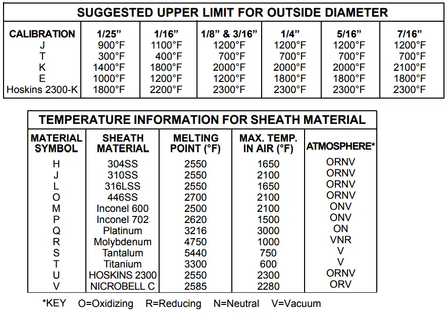
For high temperature applications 1000°F to 2300°F, new proprietary materials have been developed to perform better than the alloys used in the past.
U = HOSKINS 2300 : “…maintains special limits accuracy by up to 10 times longer than probes made from other cable.”
V = NICROBELL : “Sheathed Type N can be used to replace Platinum / Rhodium sensors up to a maximum continuous temperature of 2280°F…”
Thermocouple Temperature Limits
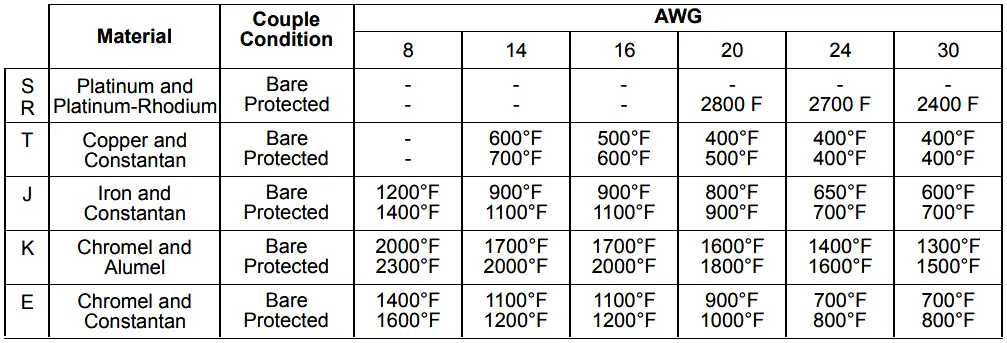
Thermoelement Material


Day today any how we are using these sensors but I don’t know how its work.