Inst ToolsInst ToolsInst Tools
  • Courses
  • Automation
    • PLC
    • Control System
    • Safety System
    • Communication
    • Fire & Gas System
  • Instrumentation
    • Design
    • Pressure
    • Temperature
    • Flow
    • Level
    • Vibration
    • Analyzer
    • Control Valve
    • Switch
    • Calibration
    • Erection & Commissioning
  • Interview
    • Instrumentation
    • Electrical
    • Electronics
    • Practical
  • Q&A
    • Instrumentation
    • Control System
    • Electrical
    • Electronics
    • Analog Electronics
    • Digital Electronics
    • Power Electronics
    • Microprocessor
  • Request
Search
  • Books
  • Software
  • Projects
  • Process
  • Tools
  • Basics
  • Formula
  • Power Plant
  • Root Cause Analysis
  • Electrical Basics
  • Animation
  • Standards
  • 4-20 mA Course
  • Siemens PLC Course
Reading: What are Switchgear Interlocks?
Share
Font ResizerAa
Inst ToolsInst Tools
Font ResizerAa
  • Courses
  • Design
  • PLC
  • Interview
  • Control System
Search
  • Courses
  • Automation
    • PLC
    • Control System
    • Safety System
    • Communication
    • Fire & Gas System
  • Instrumentation
    • Design
    • Pressure
    • Temperature
    • Flow
    • Level
    • Vibration
    • Analyzer
    • Control Valve
    • Switch
    • Calibration
    • Erection & Commissioning
  • Interview
    • Instrumentation
    • Electrical
    • Electronics
    • Practical
  • Q&A
    • Instrumentation
    • Control System
    • Electrical
    • Electronics
    • Analog Electronics
    • Digital Electronics
    • Power Electronics
    • Microprocessor
  • Request
Follow US
All rights reserved. Reproduction in whole or in part without written permission is prohibited.
Inst Tools > Blog > Electrical Basics > What are Switchgear Interlocks?

What are Switchgear Interlocks?

Learn about switchgear interlocks and their critical role in preventing hazards in electrical systems and equipment management.

Last updated: March 16, 2025 4:12 pm
Viral Nagda
Electrical Basics
No Comments
Share
6 Min Read
SHARE

You are working in an electrical system and will always ensure that no untoward incident or hazard happens either to you or the equipment nearby. This means that the electrical equipment must be operated with care. Now, as per our topic, we are relating it more to switchgear equipment which is used everywhere, be it small electrical panels or large substations. Switchgear is nothing but circuit breakers, isolators, busbars, and disconnectors, which deal with supplying and managing power to the feeder load requiring it. These switchgear devices must always be handled in such a way that it does not cause any damage, which is achievable through interlocks. In this post, we will see the concept of switchgear interlocks.

Contents
What is the purpose of switchgear interlocks?Rules of switchgear interlocksWhat are the types of switchgear interlocks?Mechanical interlocks:Electrical interlocks:

What is the purpose of switchgear interlocks?

Imagine a circuit breaker is live and you are trying to remove it in closed condition. You do not know this and if it happens, then it will lead to a major disaster or accident injuring you and the nearby equipment. So, the very first purpose of interlocks is to ensure the safe operation of switchgear. It implies that the switchgear circuit shall not be designed in such a way that it results in incorrect operation, which can put safety at risk. And when such improper operations happen, it also results in loss of money and time, because you will have to then replace the system or work on maintenance activities to restore it. So, the second and last purpose of switchgear interlocks is to avoid maintenance or replacement time and improve the overall efficiency of the system.

Rules of switchgear interlocks

Some general rules of switchgear interlocks are (according to IEC 62271-200 standards):

  1. Removable circuit breakers cannot be removed in closed condition.
  2. If there is a connection of circuit breaker and disconnector, a disconnector shall be opened only when the circuit breaker is opened first. In the reverse way, a circuit breaker shall be allowed to close only when the disconnector is closed first.
  3. Two or multiple incoming lines cannot clash with each other to give load to a feeder, otherwise it will result in a major accident.
  4. The trip functions of circuit breakers cannot be bypassed.

What are the types of switchgear interlocks?

There are two main types of switchgear interlocks are as follows.

  1. Mechanical interlocks
  2. Electrical interlocks

Mechanical interlocks:

These are simpler types of interlocks used in electrical systems. It consists of hard control keys inserted in the switchgear equipment. For example, when you want to open one switchgear, then it will allow only when the interlock switchgear’s key is inserted. And that key can be removed only when it’s switchgear is open. So, these mechanical hard keys ensure that the switchgear is opened or closed by them. The switchgear will have multiple positions, allowing the user to put the key in the required one accordingly. And when in a particular key position, other actions of the switchgear will not happen.

Electrical interlocks:

As the name implies, the switchgear electrical circuit is designed through electrical wiring interlocks, which will make or break the circuit path according to the wiring done. For example, refer to the below image for understanding. We saw a general rule earlier that two incomers cannot feed to the same load at the same time. This can be explained better through electrical interlocks.

What are Switchgear Interlocks?

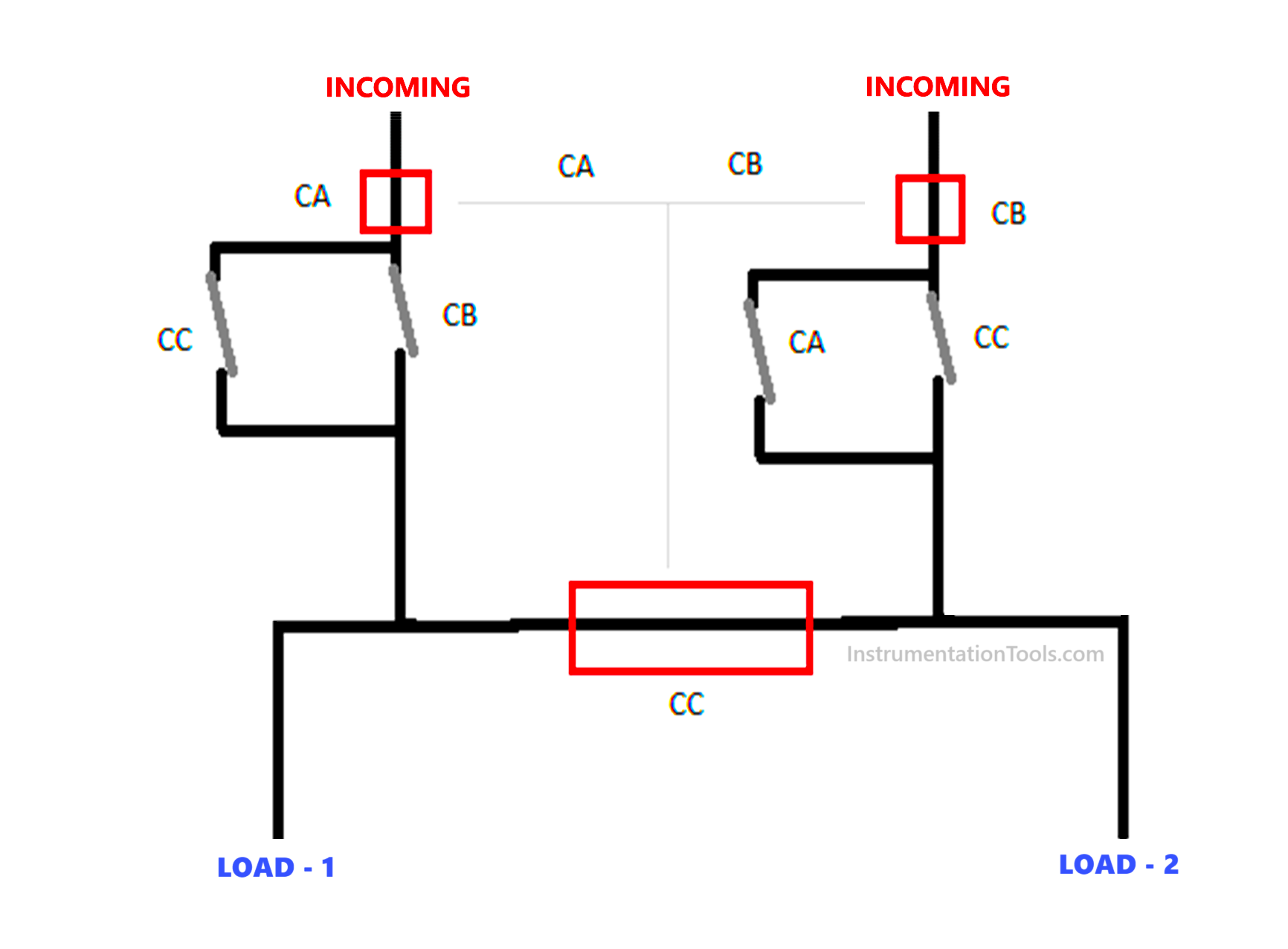
In the above image, the red box is the circuit breaker and the grey lines are the auxiliary NC contacts from the corresponding circuit breaker. The black line is the power line. As you can see, only the following conditions can work due to the wiring done:

  1. CA and CB can work with CC interlocked or not allowed to power, thus passing incoming supply to both the loads separately from both the incomers.
  2. CA and CC can work with CB interlocked or not allowed to power, thus passing incoming supply to both the loads only from CA incomer.
  3. CB and CC can work with CA interlocked or not allowed to power, thus passing incoming supply to both the loads only from CB incomer.

Due to this interlocking, open command will always remain with the third circuit breaker, and it will not allow two incomers to merge with each other. So, electrical interlocking concerns placing the correct auxiliary contacts in the path of power supply, for a safe and desired operation.

In this way, we saw the concept of switchgear interlocks.

Read Next:

  • Bus Riser in Electrical Switchgear
  • Compare Metering CT and Protection CT
  • Things to Know When Measuring Voltage
  • Charcoal and Salt in an Electrical Earth Pit
  • Electrical Engineering Problems and Analysis

Don't Miss Our Updates
Be the first to get exclusive content straight to your email.
We promise not to spam you. You can unsubscribe at any time.
Invalid email address
You've successfully subscribed !

Continue Reading

Difference between PVC, XLPE, and Insulated Cables
What is Electrical Panel Door Earth Bonding? Explained
What is Power Cable? Types of Power Cables
UPS Working Principle and Types – Offline and Online UPS Systems
Types of Circuit Breakers, Advantages, Disadvantages
Why do we need to Control the Motion using VFD drives?
Share This Article
Facebook Whatsapp Whatsapp LinkedIn Copy Link
Share
Leave a Comment

Leave a Reply Cancel reply

Your email address will not be published. Required fields are marked *

Stay Connected

128.3kFollowersLike
69.1kFollowersFollow
210kSubscribersSubscribe
38kFollowersFollow

Categories

Explore More

How Do Air Compressor Filters Clean and Protect the System?
How does SMPS Works? – Switched Mode Power Supply
What is an Instrument Transformer? – Types, Principle, Advantages
Bus Riser in Switchgear
Circuit Breaker Working Principle Animation
How Motor Star Delta Starter Works ?
PLC Panel and MCC Panel Interface Signals
Types of Motor Loads – Constant & Variable Torque, Horsepower

Keep Learning

Automatic Transfer Switch

Automatic Transfer Switch (ATS) Using Classic Control Circuit

Applications of Electrical Conduit System

What is an Electrical Conduit? – Types – How to Choose?

Star and Delta Wiring Animation

Basics of Star and Delta connections

VFD Block Diagram

What is a VFD? – Theory, Advantages, Disadvantages

Working of Stepper Motor

Types of Stepper Motors

Why Three-phase Voltage is 440 Volts

Why Three-phase Voltage is 440 Volts?

fundamentals of an AC motor

How does an Electric Motor Operate? – AC Motor Fundamentals

Difference Between Earth and Neutral

Difference Between Earth and Neutral

Learn More

Design Process Control & Safety Systems

Design View of Supplying Process Control and Safety Systems

Purpose of an Electrical Substation

What is a Substation? Purpose of an Electrical Substation

Ziegler-Nichols open-loop Tuning

Ziegler-Nichols Open-Loop Method

PLC Program for Fish Feeding System

PLC Program for Fish Feeding System

How to Run Multiple Motors with a Single VFD

How to Run Multiple Motors with a Single VFD?

Displacer Level Transmitter Intrenal Diagram

Displacer Level Transmitter Working Principle

Automatic exhaust fan control

XG5000 PLC Programming for Automatic Exhaust Fan

pH Monitoring System Triggers an Alarm

pH Monitoring System Triggers an Alarm

Menu

  • About
  • Privacy Policy
  • Copyright

Quick Links

  • Learn PLC
  • Helping Hand
  • Part Time Job

YouTube Subscribe

Follow US
All rights reserved. Reproduction in whole or in part without written permission is prohibited.
Welcome Back!

Sign in to your account

Username or Email Address
Password

Lost your password?