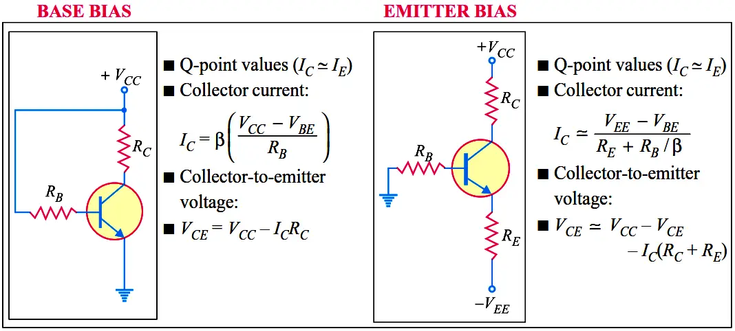
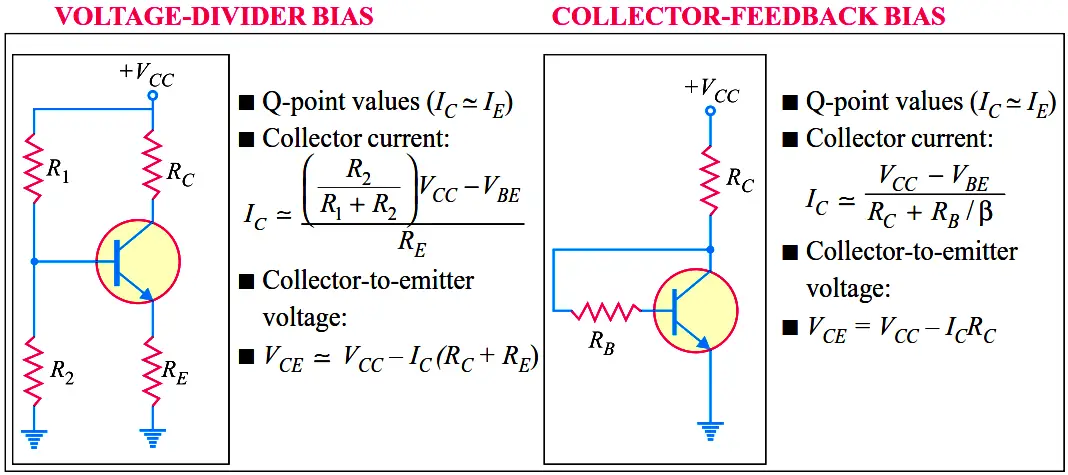
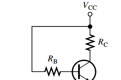
Summary Of Transistor Bias Circuits Last updated: September 27, 2016 5:33 am Editorial Staff Electronic Devices & Circuits No Comments 0 Min Read Facebook WhatsApp LinkedIn Email Telegram Reddit Twitter Subscribe In figures below, npn transistors are shown. Supply voltage polarities are reversed for pnp transistors. Facebook WhatsApp LinkedIn Email Telegram Reddit Twitter Subscribe Don't Miss Our UpdatesBe the first to get exclusive content straight to your email. We promise not to spam you. You can unsubscribe at any time.Invalid email address You've successfully subscribed ! Continue Reading Capacitively Coupled Multistage Transistor Amplifier Transistor Amplifier Working Principle Tunnel Diode Working Principle Different Types of Diodes Transistor Stabilisation Amplifiers Questions & Answers Leave a Comment Leave a Reply Cancel replyYour email address will not be published. Required fields are marked *Comment * Name * Email * Website Subscribe to our newsletter Δ Stay Connected128.3KFollowersLike69.1KFollowersFollow210KSubscribersSubscribe38KFollowersFollowCategoriesCategories Select Category Courses PLC Tutorials Root Cause Analysis (RCA) Instrumentation Interview Questions Multiple Choice Questions Animation Analyzers Basics Calibration Common Formulas Communication Control Systems Safety Instrumented System (SIS) Fire & Gas System Control Valves Solenoid Valve Standards Switches Electrical Theory Level Measurement Temperature Measurement Pressure Measurement Flow Measurement Vibration Measurement Density Measurement Practical Questions Erection & Commissioning Instrumentation Design Instrumentation MCQ Microprocessor MCQ Control Systems MCQ Digital Electronics MCQ Electronics MCQ Analog Electronics MCQ Electrical MCQ Power Electronics MCQ Power Plant Guest Articles Projects Software How It Works Process Videos Instrumentation Tools Excel Tools Books eBooks Analog Electronics Mobile App Digital Electronics Electronic Basics Electrical Q & A Electronic Devices & Circuits Electronics Animation Electronics Q & A Electrical Basics Electrical Animation Electrical Machines Power Electronics Switchgear & Protection Transmission & Distribution Power Systems Explore More Forward Bias & Reverse Bias Diode Working Animation Transistor Load Line Analysis JFET Working Animation Basics of Transistors Combining Independent Voltage Sources in Series How a Multi Color LED Works ? Basics of Amplifiers Interview Questions Capacitor Filter Operation