The Snubber circuit is one type of dv/dt protection circuit of the thyristor.
With the help of snubber circuit, the false turn-on of a thyristor due to large dv/dt can be prevented.
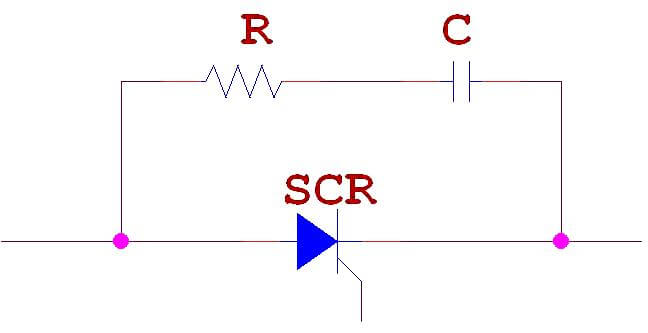
RC Snubber Circuit for SCR dv/dt Protection:
This type of snubber circuit consists of a series combination of resistance R and Capacitance C in parallel with a SCR.
Based on the above discussion we can say that simply a Capacitor C is sufficient to protect the SCR against dv/dt false triggering.
Then what is the purpose of resistance R?
In actual practice, R, C and the load current parameters should be such that
Normally R,S and load circuit parameters form an undamped circuit so that dv/dt is limited to acceptable values.
In some RC snubber circuits, a diode D used to connect in parallel with the resistor R. It is used for the purpose of bypass and thus giving improved dv/vt protection.
This article explains how to blink lights in ladder logic with a detailed explanation video…
In this article, a simple example will teach you the conversion from Boolean algebra to…
In this article, you will learn the PLC cooking timer example for kitchen automation using…
Learn an example PLC program to control a pump based on level sensors using ladder…
In the PLC timer application for security camera recording, when motion is detected then camera…
In this example, we will learn batch mixing with PLC ladder logic program using timer…

