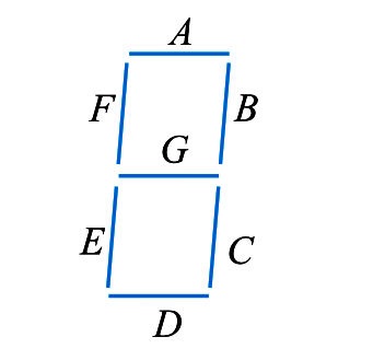
LEDs are often grouped to form seven-segment display. The below Fig. shows the front of a seven segment display. It contains seven LEDs (A, B, C, D, E, F and G) shaped in a figure of 8. Each LED is called a segment. If a particular LED is forward biased, that LED or segment will light and produces a bar of light. By forward biasing various combinations of seven LEDs, it is possible to display any number from 0 to 9. For example, if LEDs A, B, C, D and G are lit (by forward biasing them), the display will show the number 3. Similarly, if LEDs C, D, E, F, A and G are lit, the display will show the number 6. To get the number 0, all segments except G are lit.

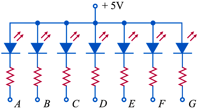
The Below Fig. shows the schematic diagram of seven-segment display. External series resistors are included to limit currents to safe levels. Note that the anodes of all seven LEDs are connected to a common positive voltage source of +5 V. This arrangement is known as common-anode type. In order to light a particular LED, say A, we ground the point A in Fig. It forward biases the LED A which will be lit.
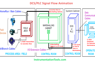
7 Segment Display Animation