Analog electronic process transmitters typically have only two calibration adjustments: one for zero and another for span. Occasionally you may find an analog electronic transmitter with a third adjustment: one for linearity.
Modern “smart” process transmitters have more components in need of adjustment. A block diagram of a typical smart pressure transmitter shows this very clearly:
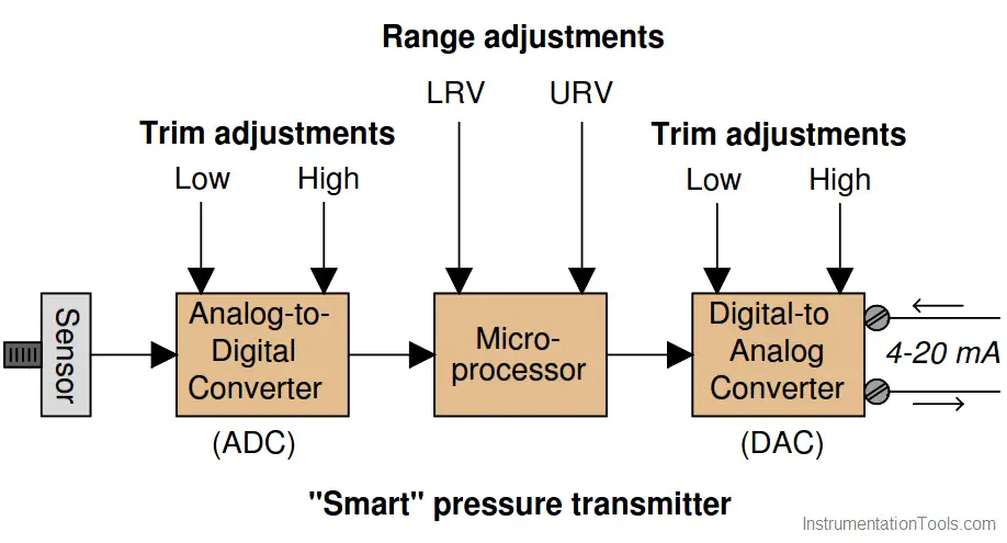
The purpose of the analog-to-digital converter (ADC) is to translate the pressure sensor’s electrical output signal into a digital number the microprocessor can understand.
Likewise, the purpose of the digital-to-analog converter (DAC) is to translate the digital output of the microprocessor into a 4 to 20 mA DC current signal representing measured pressure. The procedure of calibrating the ADC is called a sensor trim, while the process of calibrating the DAC is called an output trim.
Explain the importance of performing both a sensor trim and an output trim whenever calibrating a “smart” transmitter. In other words, explain why it is not enough to simply program LRV and URV values into the microprocessor (e.g. LRV = 0 PSI ; URV = 30 PSI) and declare the job finished.
Furthermore, explain what external calibration equipment must be connected to the transmitter to complete a sensor trim procedure, and also what external calibration equipment must be connected in order to complete an output trim procedure.
Simply setting the LRV and URV values is not actually calibrating the transmitter to accurately correspond to reality.
If this concept is hard to grasp, imagine a transmitter whose LRV and URV values are set perfectly, and whose DAC is calibrated just right, but whose ADC suffers from a zero shift. The microprocessor will “think” the pressure is something different from what it really is, and it will output an incorrect (zero-shifted) milliamp signal as a result.
In order to perform a sensor trim, you must connect a known pressure source (a standard) to the transmitter’s input port and correlate that standard pressure to the pressure value registered by the microprocessor.
When trimming the output, you must connect a precise milli-ammeter in series with the transmitter’s output current to correlate the intended current signal of the microprocessor to the actual current.
Credits: Tony R. Kuphaldt
The conveyor sorting machine is widely used in the packing industries using the PLC program…
Learn the example of flip-flop PLC program for lamps application using the ladder logic to…
In this article, you will learn the STAR DELTA programming using PLC controller to start…
Lube oil consoles of rotary equipment packages in industrial process plants are usually equipped with…
Rotating equipment packages such as pumps, compressors, turbines need the lube oil consoles for their…
This article explains how to blink lights in ladder logic with a detailed explanation video…

View Comments
Learn instrument