Inst ToolsInst ToolsInst Tools
  • Courses
  • Automation
    • PLC
    • Control System
    • Safety System
    • Communication
    • Fire & Gas System
  • Instrumentation
    • Design
    • Pressure
    • Temperature
    • Flow
    • Level
    • Vibration
    • Analyzer
    • Control Valve
    • Switch
    • Calibration
    • Erection & Commissioning
  • Interview
    • Instrumentation
    • Electrical
    • Electronics
    • Practical
  • Q&A
    • Instrumentation
    • Control System
    • Electrical
    • Electronics
    • Analog Electronics
    • Digital Electronics
    • Power Electronics
    • Microprocessor
  • Request
Search
  • Books
  • Software
  • Projects
  • Process
  • Tools
  • Basics
  • Formula
  • Power Plant
  • Root Cause Analysis
  • Electrical Basics
  • Animation
  • Standards
  • 4-20 mA Course
  • Siemens PLC Course
Reading: Semi Conductor or Piezo Resistive Strain Gauge Principle
Share
Font ResizerAa
Inst ToolsInst Tools
Font ResizerAa
  • Courses
  • Design
  • PLC
  • Interview
  • Control System
Search
  • Courses
  • Automation
    • PLC
    • Control System
    • Safety System
    • Communication
    • Fire & Gas System
  • Instrumentation
    • Design
    • Pressure
    • Temperature
    • Flow
    • Level
    • Vibration
    • Analyzer
    • Control Valve
    • Switch
    • Calibration
    • Erection & Commissioning
  • Interview
    • Instrumentation
    • Electrical
    • Electronics
    • Practical
  • Q&A
    • Instrumentation
    • Control System
    • Electrical
    • Electronics
    • Analog Electronics
    • Digital Electronics
    • Power Electronics
    • Microprocessor
  • Request
Follow US
All rights reserved. Reproduction in whole or in part without written permission is prohibited.
Inst Tools > Blog > Pressure Measurement > Semi Conductor or Piezo Resistive Strain Gauge Principle

Semi Conductor or Piezo Resistive Strain Gauge Principle

Last updated: April 14, 2019 5:32 pm
Editorial Staff
Pressure Measurement
No Comments
Share
3 Min Read
SHARE

These gauges are directly bonded (that is pasted) on the surface of the structure under study. Hence they are termed as bonded strain gauges.

The three types of bonded strain gauges are

  1. Fine wire strain gauge
  2. Metal foil strain gauge
  3. Semi-conductor strain gauge

Semi Conductor or Piezo Resistive Strain Gauge Principle

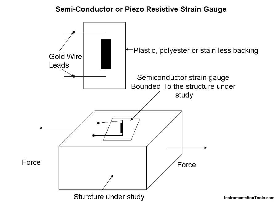
The arrangement of a semi-conductor strain gauge is as follows:

The sensing element is rectangular filament made as a wafer from silicon or geranium crystals.

To these crystals, boron is added to get some desired properties and this process is called doping and the crystals are called doped crystals.

This sensing element is attched to a plastics or stainless steel backing. Leads made of gold are drawn out from the sensing element for electrically connecting the strain gauge to a measuring instrument (wheat stone bridge).

There are two types of sensing element namely:

  • Negative or n-type (resistance decrease with respect to tensile strain).
  • Positive or P-type ( resistance increase with respect to tensile strain).

Semi Conductor or Piezo Resistive Strain Gauge Principle

Operation

With the help of an adhesive material, the strain gauge is pasted/bonded on the structure under study.

Now the structure is subjected to a force (tensile or compresive). Due to the force, the structure will change the dimension.

As the strain gauge is bonded to the structure, the stain gauge will also undergo change in both in length and cross-section (that is, it strained).

When the sensing element (crystal) of the semiconductor strain gauge is strained, its resistivity changes contributing to a change in the resistance of the strain gauge.

The change in the resistance of the strain gauge is measured using a wheat stone bridge.

This change in resistance of the strain gauge becomes a measure of the extent to which the structure is strained and a measure of the applied force when calibrated.

Advantages of semi-conductor Strain gauges

  • These gauges have high gauge factor and hence they can measure very small strains.
  • They can be manufactured to very small sizes.
  • They have an accuracy of 2.3%
  • They have excellent hysteresis characteristics.
  • They have a good frequency of response.
  • They have good fatigue life.

Limitation of semi-conductor Strain gauges

  • These gauges are brittle and hence they cannot be used for measuring large strain.
  • The gauge factor is not constant.
  • These gauges have poor linearity.
  • These gauges are very costly and are difficult to be bonded onto the structure under study.
  • These gauges are sensitive to change in temperature.
Don't Miss Our Updates
Be the first to get exclusive content straight to your email.
We promise not to spam you. You can unsubscribe at any time.
Invalid email address
You've successfully subscribed !

Continue Reading

Capacitive Type Pressure Transducers Principle
What is a Submersible Pressure Transmitter? Principle, Advantages
Differential Pressure Switch Principle
Well Manometer Principle
Advantages of Pneumatic Systems in the Automotive Industry
Pressure Transmitter Manifolds
Share This Article
Facebook Whatsapp Whatsapp LinkedIn Copy Link
Share
Leave a Comment

Leave a Reply Cancel reply

Your email address will not be published. Required fields are marked *

Stay Connected

128.3kFollowersLike
69.1kFollowersFollow
210kSubscribersSubscribe
38kFollowersFollow

Categories

Explore More

Pressure Gauge Selection
Pressure Switch Calibration Procedure
Identify the Pressure Gauge Error
Purpose of Stop in a Pressure Measuring Instrument
3 Valve Manifold Operation
Differential Pressure Transmitter Questions
Information on the Pressure Gauge Dial
What is Sensor Trim and Output Trim in Smart Transmitter?

Keep Learning

Gauge Cock

Pressure Gauge Cocks

What is a Bourdon tube

Bourdon Tube Pressure Gauge Advantages and Disadvantages

U-tube Water Manometer

How much Pressure applied to U-tube Water Manometer?

Diaphragm seal for pressure measurement device

When to use a Diaphragm Seal?

Closed Tank Liquid Level Measurement using Pressure Transmitter

Inferential Measurement based on Pressure

Absolute and Gauge Pressure

Difference Between Absolute and Gauge Pressure

Pressure Transmitter Calibration Procedure

Pressure Transmitter Calibration Procedure

piping for a Different pressure flow transmitter

Impulse Piping standards for Field instruments

Learn More

Electrical Machine Design Objective Questions and Answers

150+ Electrical Machine Design Objective Questions and Answers

What is a Network Switch?

Network Switch Requirement in SCADA and DCS Architecture

Types of Pressure

Types of Pressure – Instrument Questions and Answers

How to Install a Rotameter

How to Install a Rotameter

Capacitor Bank

Poor Power Factor Boosted – Industrial Electrical Problems

Flare KOD

Flare Knockout Drums Working Animation

Power MOSFET Safe Operating Area

Power MOSFET Safe Operating Area

Convert Linear mA to Square root mA

Convert Linear mA to Square root mA

Menu

  • About
  • Privacy Policy
  • Copyright

Quick Links

  • Learn PLC
  • Helping Hand
  • Part Time Job

YouTube Subscribe

Follow US
All rights reserved. Reproduction in whole or in part without written permission is prohibited.
Welcome Back!

Sign in to your account

Username or Email Address
Password

Lost your password?