Inst ToolsInst ToolsInst Tools
  • Ask
  • Courses
  • Videos
  • Q & A
    • Interview
      • Instrumentation
      • Electronics
      • Electrical
      • Practical Questions
    • MCQ
      • Instrumentation MCQ
      • Electrical MCQ
      • Electronics MCQ
      • Control Systems MCQ
      • Analog Electronics MCQ
      • Digital Electronics MCQ
      • Power Electronics MCQ
      • Microprocessor MCQ
      • Multiple Choice Questions
  • EE
    • Electronics
      • Electronics Q & A
      • Electronic Basics
      • Electronic Devices & Circuits
      • Electronics Animation
      • Digital Electronics
    • Electrical
      • Electrical Basics
      • Electrical Q & A
      • Power Electronics
      • Electrical Machines
      • Electrical Animation
      • Power Systems
      • Switchgear & Protection
      • Transmission & Distribution
  • Measure
    • Control Valves
    • Calibration
    • Temperature
    • Pressure
    • Flow
    • Level
    • Analyzers
    • Switches
    • Vibration
    • Solenoid Valve
  • Control
    • PLC Tutorials
    • Control Systems
    • Safety Instrumented System (SIS)
    • Communication
    • Fire & Gas System
  • More
    • Design
    • Tools
    • Animation
    • Basics
    • Formulas
    • Standards
    • TextBooks
    • Common
    • Software
    • Excel Tools
    • Erection & Commissioning
    • Process Fundamentals
    • Videos
    • Books
Search
All rights reserved. Reproduction in whole or in part without written permission is prohibited.
Reading: Scaling with Parameters (SCP) Instruction in PLC
Share
Notification Show More
Font ResizerAa
Inst ToolsInst Tools
Font ResizerAa
  • Courses
  • PLC Tutorials
  • Control Systems
Search
  • Ask
  • Courses
  • Videos
  • Q & A
    • Interview
    • MCQ
  • EE
    • Electronics
    • Electrical
  • Measure
    • Control Valves
    • Calibration
    • Temperature
    • Pressure
    • Flow
    • Level
    • Analyzers
    • Switches
    • Vibration
    • Solenoid Valve
  • Control
    • PLC Tutorials
    • Control Systems
    • Safety Instrumented System (SIS)
    • Communication
    • Fire & Gas System
  • More
    • Design
    • Tools
    • Animation
    • Basics
    • Formulas
    • Standards
    • TextBooks
    • Common
    • Software
    • Excel Tools
    • Erection & Commissioning
    • Process Fundamentals
    • Videos
    • Books
Follow US
All rights reserved. Reproduction in whole or in part without written permission is prohibited.
Inst Tools > Blog > PLC Tutorials > Scaling with Parameters (SCP) Instruction in PLC

Scaling with Parameters (SCP) Instruction in PLC

Last updated: March 4, 2021 3:24 pm
Editorial Staff
PLC Tutorials
6 Comments
Share
4 Min Read
SHARE

To study the working of Scaling with Parameters (SCP) Instruction in Allen Bradley programmable logic controllers (PLC).

Contents
Scaling with Parameters (SCP) InstructionBlock Name: SCP – Scaling with parametersInputInput MinimumInput MaximumScaled MinimumScaled MaximumFunction of SCP :Program Logic :PLC Program :Rung 0000 :Rung 0001 :Rung 0002 :Rung 0003 :Rung 0004 :Rung 0005 :Rung 0006 :Example PLC Logic with SCP InstructionWhen Level Transmitter gives 0 mA (N7:1)When Level Transmitter gives 7 mA (N7:1)When Level Transmitter gives 18 mA (N7:1)When Level Transmitter gives 20 mA (N7:1)Conclusion:

Scaling with Parameters (SCP) Instruction

Scaling with SCP Instruction

Block Name: SCP – Scaling with parameters

In the above picture, there are totally six parameter ,

Input

Integer Value address-From Field instrument which is to be scaled

Input Minimum

Minimum Input value (Ex: 4 to 20 mA from level transmitter means 4 mA is the input minimum value)

Input Maximum

Maximum Input value (Ex: 4 to 20 mA from level transmitter means 20 mA is the input maximum value)

Scaled Minimum

Minimum scale value (0 to 32767 is the maximum positive acceptable number in AB PLC-Minimum Scaled value is 0)

Scaled Maximum

Maximum scale value (0 to 32767 is the maximum positive acceptable number in AB PLC-Maximum Scaled value is 32767).

Function of SCP :

The Input value is scaled to a range determined by creating a linear relationship between input min and max values and scaled min and max values. The scaled result is returned to the address indicated by the output parameter.

Parameters may be integer, long, floating-point or immediate data values or addresses containing values. The Input value is scaled to a range determined by creating a linear relationship between input min and max values and scaled min and max values.

The scaled result is returned to the address indicated by the output parameter.

Program Logic :

Let s study the working with simple example,

Get the level of the water from level transmitter (4 to 20mA),

Give the notification

If level transmitter become faulty,

If level transmitter range between 4 to 8 mA, give the notification as water level low

If level transmitter range between 16 to 20 mA, give the notification as water level high.

If level transmitter reaches 20mA, give the notification to stop motor.

PLC Program :

Push button Latched with Memory

Rung 0000 :

Start/Stop  PB latched with memory.

Rung 0001 :

When Start is pressed move the value stored in N7:0 to N7:1

Scaling Block (SCP) in PLC

Rung 0002 :

Scaling block is used to scale the input to PLC value.(4mA -0 /20mA-32767)

Rung 0003 :

Level transmitter is configured to give 4mA when tank level is zero, if transmitter gives 0 instead of 4mA it means transmitter is faulty. Comparator block is used to compare and give notification to any one of the digital output like lamp.
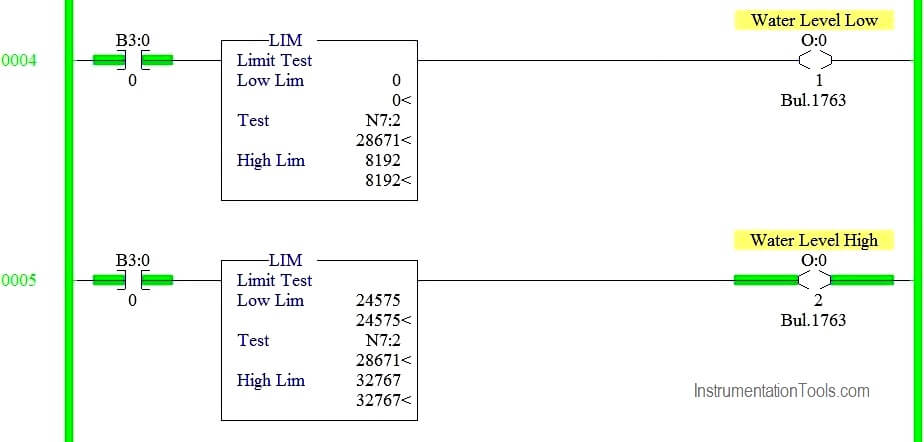
Limit Block in PLC

Rung 0004 :

Limit block is used to range the values between 4 to 8mA, and give the notification as water level is low.

Rung 0005 :

Limit block is used to range the values between 16mA to 20mA, and give the notification as water level is high.

Comparator Block in PLC

Rung 0006 :

Comparator block is used to compare the high end value and give the notification to turn stop motor.

Example PLC Logic with SCP Instruction

When Level Transmitter gives 0 mA (N7:1)

Scaling Example in PLC

When Level Transmitter gives 7 mA (N7:1)

Level Transmitter configuration in PLC

When Level Transmitter gives 18 mA (N7:1)

Scale with Parameters (SCP) Instruction
Limit Instruction in Ladder Logic

When Level Transmitter gives 20 mA (N7:1)

Working Scaling block in AB PLC
Allen Bradley Scaling Logic

Conclusion:

We can use this example to understand the working scaling block in AB PLC.

Author : Hema Sundaresan

If you liked this article, then please subscribe to our YouTube Channel for PLC and SCADA video tutorials.

You can also follow us on Facebook and Twitter to receive daily updates.

Read Next:

Single Push button Ladder Logic

Motor Logic with Push buttons

What is Latching in PLC ?

Masked Move Instruction in PLC

What is Interlocking in PLC ?

Don't Miss Our Updates
Be the first to get exclusive content straight to your email.
We promise not to spam you. You can unsubscribe at any time.
Invalid email address
You've successfully subscribed !
Automatic Coffee Vending Machine – PLC Logic Programming
Product Sticker Machine with Weighing PLC Program
Industrial Automation and Control Systems (IACS)
Edge Detection in PLC Programming
Automate Batch Mixing with Repeated Cycles in Omron PLC
Share This Article
Facebook Whatsapp Whatsapp LinkedIn Copy Link
Share
6 Comments
  • Jairo Francisco Oliveira Paula says:
    August 12, 2019 at 5:39 am

    the SPC function is an advanced level instruction in programming .. I would like posts to turn signal 4 to 20 mA through that instruction

    Reply
  • Jairo Francisco Oliveira Paula says:
    March 2, 2020 at 8:59 am

    NO RETURN TO MY QUESTION. I FOLLOW THIS PAGE FOR A LONG TIME.

    Reply
  • Jairo Francisco Oliveira Paula says:
    March 2, 2020 at 9:01 am

    Hema Sundaresan CAN ANSWER ME PLEASE!

    Reply
  • Hemalatha Sundaresan says:
    March 2, 2020 at 9:54 am

    Hello Jairo Francisco,

    I am really sorry for the late response.

    That part will be in output scaling part,where you can turn 32767 to 20mA and 0 to 4 mA.

    Reply
  • Jairo Francisco Oliveira Paula says:
    March 29, 2020 at 10:24 pm

    Thank you very much Hemalatha Sundaresan !! you could create more examples that work with signal 4 to 20 ma using the AB PLC.
    I am using this example on a temperature transmitter.cc

    Reply
  • Jone says:
    February 12, 2022 at 9:14 pm

    How I can implement level control in VBA excel?

    Reply

Leave a Reply Cancel reply

Your email address will not be published. Required fields are marked *

Stay Connected

128.3kFollowersLike
69.1kFollowersFollow
208kSubscribersSubscribe
38kFollowersFollow

Categories

Recent Comments

  • Guifty Shimica on Top Non-PLC Certification Courses for Automation Professionals
  • Guifty Shimica on Top Non-PLC Certification Courses for Automation Professionals
  • MIHARITSOA Aina Sitraka on Top Non-PLC Certification Courses for Automation Professionals
  • Vaishnavi on Free Instrumentation Course for Trainee Engineers

Related Articles

Sorting Defective Parts PLC Logic

Advanced PLC Programming for Defective Parts Sorting

plc-analog-input-card-conversion-formula

PLC Analog Input Conversion Formula

Introduction to PLC

#9 PLC Best Practices – Validate indirections

Industrial PLC Communication Network

Basics of Industrial Communication Networks

PLC Program three-phase electric motor

Identify the Problem in the PLC Program

Encode and Decode Instructions

How to Use Encode and Decode Instructions in PLC ?

different PLC brands of Distributed IO

What is Distributed IO? – Decentralized Peripherals in PLC

PLC Sizes and Applications

PLC Sizes and Applications

More Articles

Two Differential Pressure Transmitters

Pressure Level Transmitter Problems

Instrument Technician Questions and Answers

Instrument Technician Questions and Answers

Power Electronics Objective Questions

Dual Converters Multiple Choice Questions

Selecting the Proper Failure Mode

How to Select Control Valve Failure Mode

Types of Capacitors

Types of Capacitors

Transmitter Detailed Specifications

Transmitter Detailed Specifications

Circular Chart Recorder Calibration Procedure

Circular Chart Recorder Calibration Procedure

Power Systems Questions & Answers

Power Systems MCQ Series 15

Follow US
All rights reserved. Reproduction in whole or in part without written permission is prohibited.
Welcome Back!

Sign in to your account

Username or Email Address
Password

Lost your password?