Let’s study the working of SAVE and BR instructions in Siemens PLC programming.
SAVE and BR Instructions in PLC

Block Description
SAVE:
Save coil-like symbol in Siemens PLC is to saving Result of Logical Operation (RLO) into BR Memory.
BR:
BR contact like symbol in Siemens PLC is to retrieve the output to trigger any other output or block. This bit enables your program to interpret the result of a word logic operation as a binary result and to integrate this result in a binary logic string.
Let’s try to understand SAVE and BR instruction in ladder logic and FBD,
Example 1:
Turn ON Q0.0 using I0.0-When I0.0 is turning ON, it will make Q0.0 to go ON.
Ladder Logic:

Function Block Diagram (FBD):
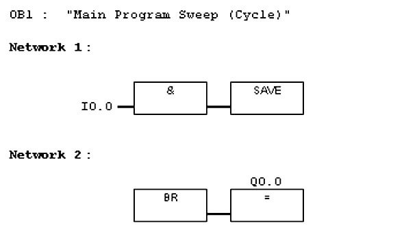
Save instruction is used to store RLO of I0.0 into BR memory bit of the status word.
By using BR contact, Q0.0 is turned ON.
Example 2:
Turn ON Q0.0 using I0.0 and Q0.1 using I0.1- When input I0.0 is turning ON it will make output Q0.0 to go ON and input I0.1 is turning ON it will make output Q0.1 to go ON.
Ladder Logic:

Function Block Diagram (FBD):

First Save instruction in network 1 is used to store RLO of input I0.0 into BR memory bit of the status word. By using BR contact, output Q0.0 is turned ON.
Second Save instruction in network 3 is used to store RLO of input I0.1 into BR memory bit of the status word. By using BR contact, output Q0.1 is turned ON.
Example 3:
Turn ON Q0.0, Q0.1 and Q0.2 using I0.0 – When input I0.0 is turning ON it will make output Q0.0, Q0.1 and Q0.2 to go ON.
Ladder Logic

Function Block Diagram (FBD):

Save instruction in network 1 is common for all the BR memory we have used in Networks 2, 3 and 4.
Author: Hema Sundaresan
If you liked this article, then please subscribe to our YouTube Channel for PLC and SCADA video tutorials.
You can also follow us on Facebook and Twitter to receive daily updates.
Read Next:
- PLC Programming Examples
- Types of Scan Cycles in PLC
- Packaging Process using PLC
- Documentation of PLC Systems
- Programming of Pumps Logic


sir I can’t add br open contact its says wrong name what to do