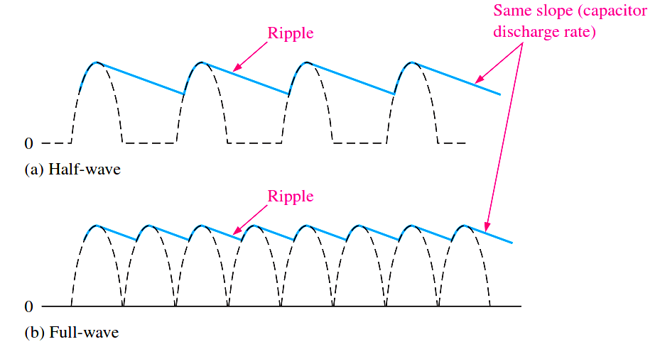
Ripple Voltage As you have seen, the capacitor quickly charges at the beginning of a cycle and slowly discharges through RL after the positive peak of the input voltage (when the diode is reverse-biased). The variation in the capacitor voltage due to the charging and discharging is called the ripple voltage. Generally, ripple is undesirable; thus, the smaller the ripple, the better the filtering action, as illustrated in Below Figure.

Fig : Half-wave ripple voltage (blue line).
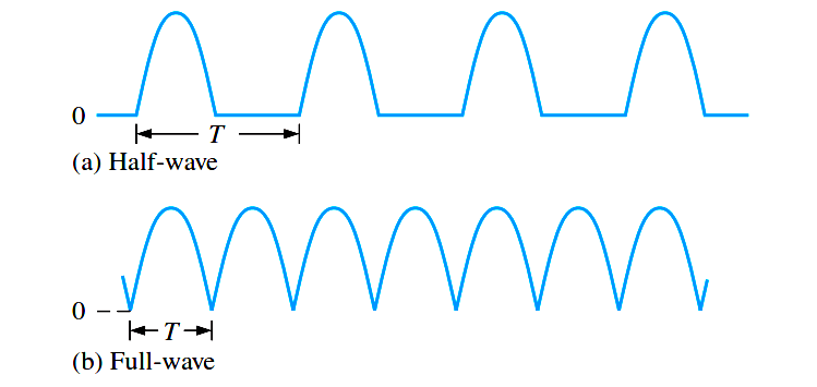
For a given input frequency, the output frequency of a full-wave rectifier is twice that of a half-wave rectifier, as illustrated in Figure 1. This makes a full-wave rectifier easier to filter because of the shorter time between peaks. When filtered, the full-wave rectified voltage has a smaller ripple than does a half-wave voltage for the same load resistance and capacitor values. The capacitor discharges less during the shorter interval between full-wave pulses, as shown in Figure 2.
Fig 1 : The period of a full-wave rectified voltage is half that of a half-wave rectified voltage. The output frequency of a full-wave rectifier is twice that of a half-wave rectifier.
Fig 2 : Comparison of ripple voltages for half-wave and full-wave rectified voltages with the same filter capacitor and load and derived from the same sinusoidal input voltage.
Ripple Factor
The ripple factor (r) is an indication of the effectiveness of the filter and is defined as
where Vr(pp) is the peak-to-peak ripple voltage and VDC is the dc (average) value of the filter’s output voltage, as illustrated in Below Figure. The lower the ripple factor, the better the filter. The ripple factor can be lowered by increasing the value of the filter capacitor or increasing the load resistance.
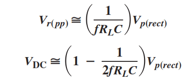
For a full-wave rectifier with a capacitor-input filter, approximations for the peak-to-peak ripple voltage, Vr(pp), and the dc value of the filter output voltage, VDC, are given in the following equations. The variable Vp(rect) is the unfiltered peak rectified voltage. Notice that if RL or C increases, the ripple voltage decreases and the dc voltage increases.

