Diaphragm seals or Remote Seal Differential Pressure Transmitters are traditionally used when a standard pressure transmitter should not be exposed to the process pressure directly.
Diaphragm seals typically protect the pressure transmitter from one or more damaging aspects of the process media.
Consideration for using a diaphragm seal should be made in the following circumstances.
How Do Seal Systems Work?
Diaphragm seal systems respond to changes in both process pressures as the level changes in the tank, and in static pressure over the liquid. These variations in pressure are transmitted through an oil- filled capillary to a differential pressure transmitter-sensor. The capillaries and seals are filled with incompressible oil compatible with the process temperature, pressure, and media composition. The transmitter is commonly mounted at grade, or in close proximity to the high-pressure process connection. The change in level in tank or vessel inturn effects the HP & LP pressure points and this change in pressure will be measured using a differential pressure transmitter and then calculates equivalent level of the tank or vessel.
For applications under vacuum, the transmitter is mounted below the high-pressure connection to reduce vacuum effects on the transmitter fill fluid. The minimum capillary length is dictated by the distance between the mounting position of the transmitter and the low-pressure connection. All cavities within the assembly are oil-filled including the diaphragm, capillary, and transmitter body. Although manufacturing techniques help ensure a high-quality fill, temperature-induced errors are inherent to diaphragm seal systems.
Remote Seal Differential Pressure Transmitters Calculations
Liquid Level Measurement : Closed Tank
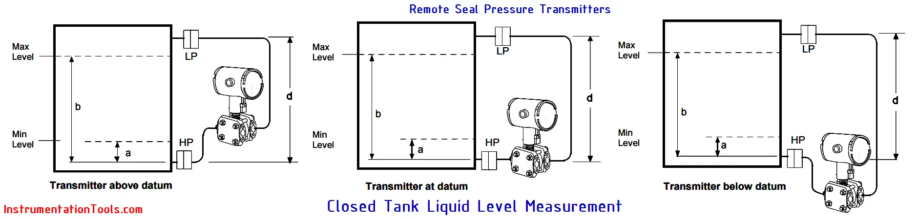
Determine the minimum and maximum pressure differentials to be measured
At Minimum Level i.e.
PMin = (SGp x a) – (SGf x d)
i.e. LRV when HP at bottom of tank
i.e. –URV when LP at bottom of tank
PMax = (SGp x b) – (SGf x d)
i.e. URV when HP at bottom of tank
i.e. –LRV when LP at bottom of tank
Where:
minimum level at 4mA
maximum level at 20 mA
a = distance between bottom tap and minimum level
b = distance between bottom tap and maximum level
d = distance between taps
SGf = Specific Gravity of capillary fill fluid
SGp = Specific Gravity of process fluid
Density or Interface Measurement
Calculate the minimum and maximum pressure differentials to be measured
Pmin = (SGmin – SGf) x (d);
minimum density, 4mA output
Pmax = (SGmax – SGf) x (d);
maximum density, 20mA output
Where: d = distance between the taps
SGmax = maximum Specific Gravity
SGmin = minimum Specific Gravity
SGf = Specific Gravity of capillary fill fluid
Note: The Pmin & Pmax are nothing but LRV & URV of the transmitters. These to be calculated and entered in the Remote seal DP Transmitter during calibration.
Article Source: Honeywell & Rosemount
In this article, a simple example will teach you the conversion from Boolean algebra to…
In this article, you will learn the PLC cooking timer example for kitchen automation using…
Learn an example PLC program to control a pump based on level sensors using ladder…
In the PLC timer application for security camera recording, when motion is detected then camera…
In this example, we will learn batch mixing with PLC ladder logic program using timer…
This PLC example on manufacturing line assembly is an intermediate-level PLC program prepared for the…


View Comments
Hai sir i am I need dp transmitter calibration for close tank in impulse line
What is autoguide....
The FP range calculation is not correct / clear to me if the capillary type transmitter is mounted above the HP tapping ie Level zero by say 2 meter. Please furnish LRV calculation for this