How does a Redundant Controller comes in line when the Main Controller fails in the distributed control system (DCS)?
The Processor Card performs calculations and control computation. In case of Field Control Station (FCS) (simply we can assume as a System Cabinet with Processor cards & other IO cards) with duplexed configuration, there are two processor cards. One of the cards is in control status (main) and the other is in the standby status.
In case of FCS with duplexed configuration, both the processor cards perform control computation.
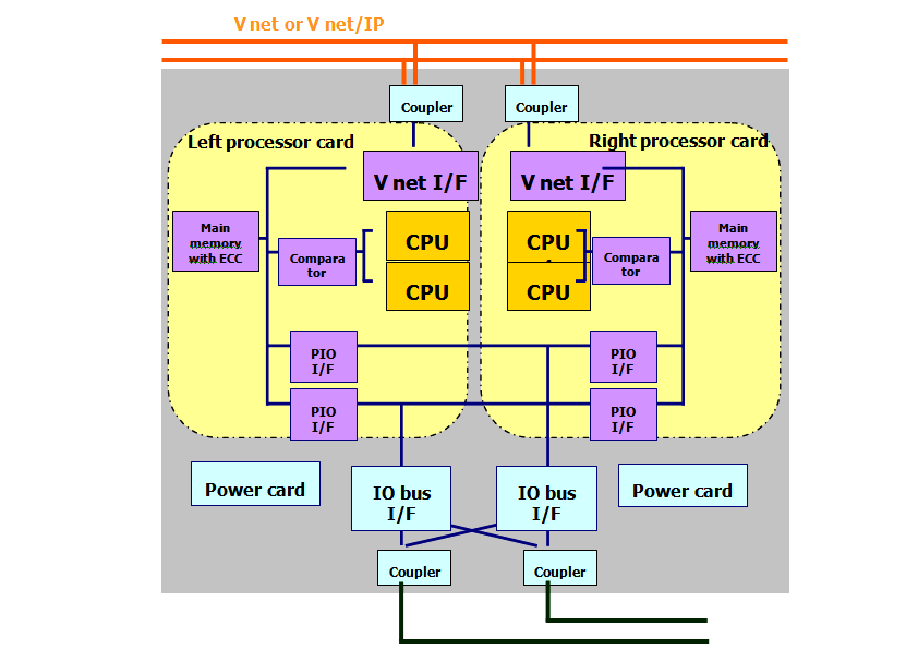
From the below figure, we have Left Processor Card and Right Processor Card. Again each processor card has two inbuilt processors or CPU, which perform the same control computation (optional feature, some cards may have only one, depends on manufacturer).
By Default, One Processor Card (say Right CPU) will be main and Other (Left) card is in Standby mode during Start-up.
All Inputs & outputs will be shared among the Two Processor Cards (Left & Right). The same program will be downloaded into both Cards (left & Right).
As per below figure, Both Left & Right Processor Cards have two Sub CPU’s inside. The two sub CPU’s in each Processor Card (Left or Right) executes same functions.
A comparator compares the computation results during each computation cycle of these CPU’s. If the results match computation is normal and the data is sent to locations such as the main memory and bus interface unit for further processing to take respective action. If the results do not match, the corresponding processor card will be stopped.
If the error occurs in the active (main) processor card, then switchover to standby card occurs without any interruption to live monitor/control of the plant.

Image Courtesy : Yokogawa
In this post, we will learn the basic requirements for a network switch to be…
The PLC panel and MCC panel interface signals are start, stop, run feedback, trip, local…
In this article, we are going to discuss about shutter door control using induction motor…
Electrical Drives control the motion of electric motors. Motion control is required in industrial and…
PLC ladder logic design to control 3 motors with toggle switch and explain the program…
VFD simulator download: Master the online tool from the Yaskawa V1000 & programming software for…
View Comments
How does it know which processor is giving the error signal ?