Inst ToolsInst ToolsInst Tools
  • Courses
  • Automation
    • PLC
    • Control System
    • Safety System
    • Communication
    • Fire & Gas System
  • Instrumentation
    • Design
    • Pressure
    • Temperature
    • Flow
    • Level
    • Vibration
    • Analyzer
    • Control Valve
    • Switch
    • Calibration
    • Erection & Commissioning
  • Interview
    • Instrumentation
    • Electrical
    • Electronics
    • Practical
  • Q&A
    • Instrumentation
    • Control System
    • Electrical
    • Electronics
    • Analog Electronics
    • Digital Electronics
    • Power Electronics
    • Microprocessor
  • Request
Search
  • Books
  • Software
  • Projects
  • Process
  • Tools
  • Basics
  • Formula
  • Power Plant
  • Root Cause Analysis
  • Electrical Basics
  • Animation
  • Standards
  • 4-20 mA Course
  • Siemens PLC Course
Reading: Rate Compensated Heat Detectors Working Principle
Share
Font ResizerAa
Inst ToolsInst Tools
Font ResizerAa
  • Courses
  • Design
  • PLC
  • Interview
  • Control System
Search
  • Courses
  • Automation
    • PLC
    • Control System
    • Safety System
    • Communication
    • Fire & Gas System
  • Instrumentation
    • Design
    • Pressure
    • Temperature
    • Flow
    • Level
    • Vibration
    • Analyzer
    • Control Valve
    • Switch
    • Calibration
    • Erection & Commissioning
  • Interview
    • Instrumentation
    • Electrical
    • Electronics
    • Practical
  • Q&A
    • Instrumentation
    • Control System
    • Electrical
    • Electronics
    • Analog Electronics
    • Digital Electronics
    • Power Electronics
    • Microprocessor
  • Request
Follow US
All rights reserved. Reproduction in whole or in part without written permission is prohibited.
Inst Tools > Blog > Fire & Gas System > Rate Compensated Heat Detectors Working Principle

Rate Compensated Heat Detectors Working Principle

Last updated: February 26, 2019 8:35 pm
Editorial Staff
Fire & Gas System
No Comments
Share
2 Min Read
SHARE

Rate compensated heat detectors are designed to initiate an alarm when the temperature of the surrounding air reaches a predetermined level, regardless of the rate of temperature rise.

Contents
Rate Compensated Heat DetectorsAdvantages of Rate Compensated Heat detectors:Disadvantages of Rate Compensated Heat detectors:

Rate Compensated Heat Detectors

Rate-compensated heat or thermal detectors are devices that are designed to activate at a predetermined temperature in a space regardless of the rate at which the temperature in the space increases.

This is accomplished by compensating for the thermal lag between the room temperature and the interior of the device.

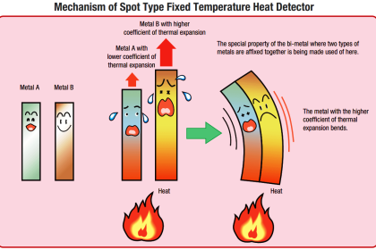
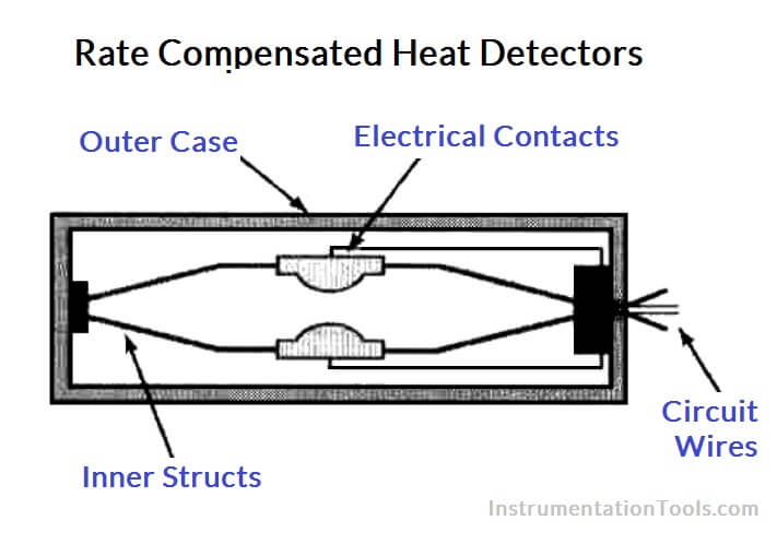
Construction consists of an outer metal tube that expands at a fixed rate. Within this tube, alarm contacts close when a certain expansion distance is reached, but this expansion is opposed by another metal device.

Rate Compensated Heat Detectors Working Principle

At a slow rate-of-rise in temperature, the outer tube expands drawing the contacts closer together.

The inner metal device exerts a counter force, keeping the contacts separated until the entire device has been heated to its rated temperature.

At a rapid rate-of-rise in temperature, the outer tube expands faster than the inner device can compensate.

Therefore, the alarm contacts close when the entire device has been heated to a lower level, thus compensating for thermal lag.

These detectors are designed to eliminate the thermal lag associated with a fixed temperature detector as well as the problem of false alarms and the risk of missing slow heat release combustion that are inherent with rate-of-rise detectors.

Advantages of Rate Compensated Heat detectors:

  • Responds accurately and positively to fire threats
  • Virtually eliminates false alarms
  • Not affected by dusty or dirty environments
  • More reliable than a smoke detector
  • Less expensive than smoke detector units
  • Minimal maintenance

Disadvantages of Rate Compensated Heat detectors:

  • Slower to respond than smoke detectors
  • Will not detect products of combustion
  • Only suitable for protection of property
Articles You May Like :

Fire Detection System

Oxygen Safety Analyzer

Catalytic Type Gas Sensor

Fire Extinguishers Mock Test

Basics of Sprinkler System

Don't Miss Our Updates
Be the first to get exclusive content straight to your email.
We promise not to spam you. You can unsubscribe at any time.
Invalid email address
You've successfully subscribed !

Continue Reading

How to identify location of Fire Detectors
Gas Detectors Working Principle
Types of Fire and Gas Detectors
What is Lower Explosive Limit & Upper Explosive Limit ?
Industrial Flame Detectors
Basics of Gas Monitoring
Share This Article
Facebook Whatsapp Whatsapp LinkedIn Copy Link
Share
Leave a Comment

Leave a Reply Cancel reply

Your email address will not be published. Required fields are marked *

Stay Connected

128.3kFollowersLike
69.1kFollowersFollow
210kSubscribersSubscribe
38kFollowersFollow

Categories

Explore More

Smoke Detector Testing Procedure
Fire Water Sprinklers Working Principle
Fire and Gas System Loop Checks Procedure
Basics of Fire Fighting Hydrant Systems
Sensor Technologies in Gas Detectors
Why Fire and Gas Detectors are 3-Wire types instead of 2 Wire?
Why LEL important in Gas Detection?
Chlorine Gas Hazards

Keep Learning

Carbon Monoxide Gas Hazards

Carbon Monoxide Gas Hazards

Lower Explosive Limit (LEL)

Lower Explosive Limit (LEL)

Argonite/CO2 Flooding System Master & Slave Cylinder Operation

Infrared Hydrocarbon Gas Detector Calibration Procedure

Infrared Hydrocarbon Gas Detector Calibration Procedure

Purpose of End of Line (EOL) Resistor in Fire & Gas System ?

Why we use End of Line (EOL) Resistor in Fire and Gas System ?

Design Basis for Fire Detection and Alarm System

Design Basis for Fire Detection and Alarm System

Fire-Triangle-in-Gas-Detection-System

Basics of Fire Detection System

oxygen Safety Analyzer

Oxygen Safety Analyzer

Learn More

Flare KOD

Flare Knockout Drums Working Animation

Transformer Efficiency and Loses Formula

Transformer Losses and Efficiency

PID Controller Graph - 3

PID Controllers Graphical Analysis

open vs closed loop

Open Loop and Closed Loop Animation

Ball Valve Pictures

How Ball Valves Work ?

BJT Amplifiers Interview Questions & Answers

BJT Amplifiers Interview Questions & Answers

PLC Program for fan control unit system

PLC Programming for Fan Control Unit System for Industry

Configure Analog Inputs and Outputs in Delta PLC

How to Configure Analog Inputs and Outputs in Delta PLC?

Menu

  • About
  • Privacy Policy
  • Copyright

Quick Links

  • Learn PLC
  • Helping Hand
  • Part Time Job

YouTube Subscribe

Follow US
All rights reserved. Reproduction in whole or in part without written permission is prohibited.
Welcome Back!

Sign in to your account

Username or Email Address
Password

Lost your password?