Programmable Logic Controller Questions and Answers
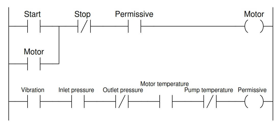
The following PLC program was written to control the operation of a large electric motor-driven pump. A variety of “permissive” inputs protect the pump from damage under abnormal conditions:

Identify the type of contact (either NO or NC) necessary for each of these electrical switch contacts, based on the trip condition (either high or low) and how each input is applied in the PLC program:
A helpful problem-solving technique is to first identify the necessary coloring which will allow the motor to run (i.e. the condition of all permissives during correct operating conditions):
We know the NO contact instruction labeled “Permissive” in the upper rung needs to be colored if ever the “Motor” coil instruction is to receive color.
This means the entire series string of contact instructions in the second rung needs to be colored under proper operating conditions.
Once we know this, we may determing the necessary “normal” statuses of all permissive switches in order to make their corresponding PLC program contact instructions colored. A few examples will be given here:
The PLC contact instruction for this permissive is normally-open, which means that PLC input must be energized with electricity in order to color that contact instruction.
This means the high vibration switch must be in the closed condition while everything is running as it should (i.e. low vibration), and open if vibration becomes excessive.
A vibration switch that is closed when vibration is below the trip threshold is a normally-closed (NC) vibration switch.
The PLC contact instruction for this permissive is normally-open, which means that PLC input must be energized with electricity in order to color that contact instruction.
This means the low inlet pressure switch must be in the closed condition while everything is running as it should (i.e. adequate inlet pressure), and open if inlet pressure becomes too low.
A pressure switch that is open when pressure is below the trip threshold is a normally-open (NO) pressure switch.
The PLC contact instruction for this permissive is normally-closed, which means that PLC input must be de-energized in order to color that contact instruction.
This means the high outlet pressure switch must be in the open condition while everything is running as it should (i.e. moderate outlet pressure), and close if outlet pressure becomes excessive.
A pressure switch that is open when pressure is below the trip threshold is a normally-open (NO) pressure switch.
Share Your Answer / Comments
Credits : by Tony R. Kuphaldt – under CC BY 1.0
If you liked this article, then please subscribe to our YouTube Channel for PLC and SCADA video tutorials.
You can also follow us on Facebook and Twitter to receive daily updates.
Read Next:
Learn an example PLC program to control a pump based on level sensors using ladder…
In the PLC timer application for security camera recording, when motion is detected then camera…
In this example, we will learn batch mixing with PLC ladder logic program using timer…
This PLC example on manufacturing line assembly is an intermediate-level PLC program prepared for the…
In this article, you will learn the PLC programming example with pushbutton and motor control…
This article teaches how to convert Boolean logic to PLC programming ladder logic with the…
View Comments
Hello and thanks for the interesting arcticles that you post .I would to like to ask something because i m a bit confused .I can't understand why he uses n.o contact for high pressure and XIO in PLC? Wouldn't be more safe to use n.c contact for high pressure and XIC in PlC? In a case of a loss of the cable the motor won't cut from high outlet pressure . Thanks
This ladder diagram is excellent . Send me more ladder diagram.
Dears,
The Interlocking is good but one mistake still exists and that is stop push button must be in NC else it will not run.
I agree with M Iabal
I'm interested in training the PLC programming Automation
I am plc working and full and fully interested so while all control and interlocking circuit improve tha movement