Inst ToolsInst ToolsInst Tools
  • Courses
  • Automation
    • PLC
    • Control System
    • Safety System
    • Communication
    • Fire & Gas System
  • Instrumentation
    • Design
    • Pressure
    • Temperature
    • Flow
    • Level
    • Vibration
    • Analyzer
    • Control Valve
    • Switch
    • Calibration
    • Erection & Commissioning
  • Interview
    • Instrumentation
    • Electrical
    • Electronics
    • Practical
  • Q&A
    • Instrumentation
    • Control System
    • Electrical
    • Electronics
    • Analog Electronics
    • Digital Electronics
    • Power Electronics
    • Microprocessor
  • Request
Search
  • Books
  • Software
  • Projects
  • Process
  • Tools
  • Basics
  • Formula
  • Power Plant
  • Root Cause Analysis
  • Electrical Basics
  • Animation
  • Standards
  • 4-20 mA Course
  • Siemens PLC Course
Reading: PLC Electric Motor Interlocks
Share
Notification Show More
Font ResizerAa
Inst ToolsInst Tools
Font ResizerAa
  • Courses
  • Design
  • PLC
  • Interview
  • Control System
Search
  • Courses
  • Automation
    • PLC
    • Control System
    • Safety System
    • Communication
    • Fire & Gas System
  • Instrumentation
    • Design
    • Pressure
    • Temperature
    • Flow
    • Level
    • Vibration
    • Analyzer
    • Control Valve
    • Switch
    • Calibration
    • Erection & Commissioning
  • Interview
    • Instrumentation
    • Electrical
    • Electronics
    • Practical
  • Q&A
    • Instrumentation
    • Control System
    • Electrical
    • Electronics
    • Analog Electronics
    • Digital Electronics
    • Power Electronics
    • Microprocessor
  • Request
Follow US
All rights reserved. Reproduction in whole or in part without written permission is prohibited.
Inst Tools > Blog > PLC Tutorials > PLC Electric Motor Interlocks

PLC Electric Motor Interlocks

Last updated: March 4, 2021 4:51 pm
Editorial Staff
PLC Tutorials Practical Questions
7 Comments
Share
4 Min Read
SHARE

Programmable Logic Controller Questions and Answers

Contents
PLC Electric Motor InterlocksAnswer :High vibration:Low inlet pressure:High outlet pressure:

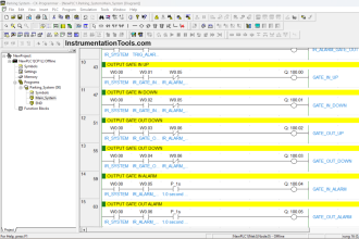
The following PLC program was written to control the operation of a large electric motor-driven pump. A variety of “permissive” inputs protect the pump from damage under abnormal conditions:

PLC Electric Motor Interlocks

PLC Electric Motor Interlocks

Identify the type of contact (either NO or NC) necessary for each of these electrical switch contacts, based on the trip condition (either high or low) and how each input is applied in the PLC program:

  1. Start pushbutton = NO or NC?
  2. Stop pushbutton = NO or NC?
  3. High vibration = NO or NC?
  4. Low inlet pressure = NO or NC?
  5. High outlet pressure = NO or NC?
  6. High motor temperature = NO or NC?
  7. High pump temperature = NO or NC?

Answer :

  1. Start pushbutton = NO
  2. Stop pushbutton = NO
  3. High vibration = NC
  4. Low inlet pressure = NO
  5. High outlet pressure = NO
  6. High motor temperature = NC
  7. High pump temperature = NO

A helpful problem-solving technique is to first identify the necessary coloring which will allow the motor to run (i.e. the condition of all permissives during correct operating conditions):

PLC Motor Permissive

We know the NO contact instruction labeled “Permissive” in the upper rung needs to be colored if ever the “Motor” coil instruction is to receive color.

This means the entire series string of contact instructions in the second rung needs to be colored under proper operating conditions.

Once we know this, we may determing the necessary “normal” statuses of all permissive switches in order to make their corresponding PLC program contact instructions colored. A few examples will be given here:

High vibration:

The PLC contact instruction for this permissive is normally-open, which means that PLC input must be energized with electricity in order to color that contact instruction.

This means the high vibration switch must be in the closed condition while everything is running as it should (i.e. low vibration), and open if vibration becomes excessive.

A vibration switch that is closed when vibration is below the trip threshold is a normally-closed (NC) vibration switch.

Low inlet pressure:

The PLC contact instruction for this permissive is normally-open, which means that PLC input must be energized with electricity in order to color that contact instruction.

This means the low inlet pressure switch must be in the closed condition while everything is running as it should (i.e. adequate inlet pressure), and open if inlet pressure becomes too low.

A pressure switch that is open when pressure is below the trip threshold is a normally-open (NO) pressure switch.

High outlet pressure:

The PLC contact instruction for this permissive is normally-closed, which means that PLC input must be de-energized in order to color that contact instruction.

This means the high outlet pressure switch must be in the open condition while everything is running as it should (i.e. moderate outlet pressure), and close if outlet pressure becomes excessive.

A pressure switch that is open when pressure is below the trip threshold is a normally-open (NO) pressure switch.

Share Your Answer / Comments

Credits : by Tony R. Kuphaldt – under CC BY 1.0

For More PLC Questions : CLICK HERE

If you liked this article, then please subscribe to our YouTube Channel for PLC and SCADA video tutorials.

You can also follow us on Facebook and Twitter to receive daily updates.

Read Next:

  • PLC Pump Permissive Interlocks
  • Permissive and Interlock Circuits
  • Basics of Trips, Interlocks, Permissives & Sequences
  • Troubleshooting PLC Permissive Inputs
  • PLC Permissive for Motor Control
Don't Miss Our Updates
Be the first to get exclusive content straight to your email.
We promise not to spam you. You can unsubscribe at any time.
Invalid email address
You've successfully subscribed !

Continue Reading

PLC based Drink Dispenser System
Interconnection between PLC, MCC, LCP & Pumps – Video
Schneider PLC Example: Control Lamps Sequences
Wood Sawing and Blower System: PLC Control Design
Demo of a SCADA Software – Level Control System
PLC Program for Stage Control: Curtains and Stage Elevation
Share This Article
Facebook Whatsapp Whatsapp LinkedIn Copy Link
Share
7 Comments
  • Dimitris says:
    September 1, 2017 at 5:04 pm

    Hello and thanks for the interesting arcticles that you post .I would to like to ask something because i m a bit confused .I can’t understand why he uses n.o contact for high pressure and XIO in PLC? Wouldn’t be more safe to use n.c contact for high pressure and XIC in PlC? In a case of a loss of the cable the motor won’t cut from high outlet pressure . Thanks

    Reply
  • Debabrata Rout says:
    January 28, 2019 at 6:09 pm

    This ladder diagram is excellent . Send me more ladder diagram.

    Reply
  • M Iqbal says:
    March 10, 2019 at 10:06 pm

    Dears,

    The Interlocking is good but one mistake still exists and that is stop push button must be in NC else it will not run.

    Reply
  • chuangbing chen says:
    March 30, 2021 at 6:06 pm

    I agree with M Iabal

    Reply
  • Alfred G Kebbie says:
    February 19, 2022 at 5:58 pm

    I’m interested in training the PLC programming Automation

    Reply
  • J.BALAJI says:
    September 3, 2022 at 6:20 am

    I am plc working and full and fully interested so while all control and interlocking circuit improve tha movement

    Reply
  • Rotimi Adeyeye says:
    April 23, 2025 at 7:39 pm

    A button to ON lamp same button to OFF the lamp.

    Reply

Leave a Reply Cancel reply

Your email address will not be published. Required fields are marked *

Stay Connected

128.3kFollowersLike
69.1kFollowersFollow
210kSubscribersSubscribe
38kFollowersFollow

Categories

Explore More

Allen Bradley SLC 500 PLC Programming
Developing PLC Logic for Water Pumping and Chemical Addition
Paint Mixing System
Displacer Level Transmitter Question & Answer
Down Counter PLC Program
Oil and Water Separation Process using PLC Programming
Calculate Hydraulic System Fluid Pressure
How to Create Faceplate in FactoryTalk View Studio?

Keep Learning

Omron PLC real-time clock street lighting program

Automatic Highway Lights Program using RTC in Omron PLC

Shift Bit Register in PLC

Shift Bit Register in PLC

Convert an Electrical Diagram into PLC Program

How to Convert an Electrical Diagram into PLC Program?

Motor Library in Studio 5000 PLC

Create User-Defined Data Types and Function Blocks in Studio 5000

Dual-junction thermocouple circuit

Find Thermocouple Ouput Voltage

Siemens PLC Simulator and Plant Simulation Software

How to use Simulator in Siemens PLC?

PID block from the PLC library

How to Configure PID Controller in Various Schneider PLCs?

Does Really a Safety Barrier is Important

Does Really a Safety Barrier is Important? – PLC DCS Systems

Learn More

Three Phase To Single Phase Wiring Connections

Single Phase Power Wiring Schemes

Ultrasonic Flow Meters Working Principle

Ultrasonic Flow Meters Working Principle

Piston Type Flow Meter Principle

Types of Variable Area Flow Meters

Current Divider Rule

Current Divider Rule

quantum computer

Vacuum Technology is Enabling New Era of Ultra-Powerful Computers: Quantum Computing

Technical Specification for Uninterrupted Power Supply (UPS) System

Technical Specification for Uninterrupted Power Supply (UPS) System

Electrical Cabinet Air Conditioner

Electrical Cabinet Air Conditioner – Enclosure Cooling, Maintenance

Use of Isolators and Barriers in Electrical Panel

Use of Isolators and Barriers in Electrical Panel

Menu

  • About
  • Privacy Policy
  • Copyright

Quick Links

  • Learn PLC
  • Helping Hand
  • Part Time Job

YouTube Subscribe

Follow US
All rights reserved. Reproduction in whole or in part without written permission is prohibited.
Welcome Back!

Sign in to your account

Username or Email Address
Password

Lost your password?