Profibus Listener is nothing but a profibus display unit or an indicator unit.
The profibus Indicator is able to operate in a “Listener” mode whereby it does not appear as a device on the network, but simply listens for appropriate data on the segment it is connected to. All configuration must be performed locally, but thereafter it imposes no overhead on the network. This mode is useful where timing is critical, in retrofit applications or when node licensing costs need to be minimised.
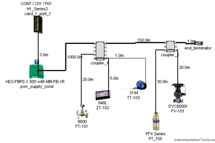
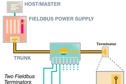
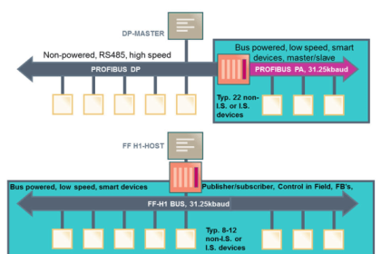
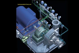
It is necessary to have a basic understanding of how data on a Profibus system is passed between the host and the devices. As a general rule a Profibus PA segment will be connected to a Profibus DP network and controller, via a segment coupler. The segment coupler adjusts the communication speed and signalling so that the PA devices are visible to the controlling host and software.
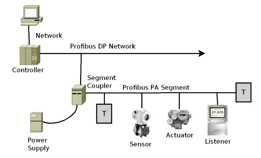
Image Courtesy : Beka
Each device attached to the segment has a physical address between 1 and 125 with address 1 or 2 being reserved for the controller. To make a process happen, the controller will read data from a number of instruments, it will process the data and finally write the data out to other devices in order to keep the process running smoothly. It is the data that is being “read from” and “written to” the devices on the segment that the listener can tap into.
In order to capture the data, we need to know how to locate it. When each device is loaded on to the segment it has a number of “Slots” in which the plant engineer places a software module representing the data that the slot is capable of dealing with. e.g. a SP Module consists of a 4 byte floating point number and a status byte. (known as a DS-33 data type).
The following example shows a temperature transmitter with two slots, the first one represents the temperature read from the external sensor, the second one represents the body temperature used for CJ compensation:
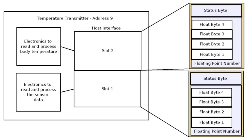
Image Courtesy : Beka
The plant engineer has set the address to 9 and loaded a SP module into both slots on the device. The slot data for a device is read in one go. Therefore a read of the device at address 9 with consist of 10 bytes containing a float with its status followed by another float with its status. The first item of data will start at Address 9 index 0 while the second value, status combination will start at Address 9 index 5. This address and index data is available to the plant engineer on the programming workstation for the host. When data is transmitted by the host it takes the form of Source_Address,Destination_Address and Data.
The profibus listener uses this information to display the value that the user wants to view. The user simply sets up the Source Address, Destination Address and the Index into the data packet. In the above example, setting a source address of 9, a destination address of 1 (Host Controller) and an Index of 5 would point at the second DS-33 data block i.e. the body temperature.
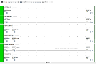
The following example gives the 7 steps to display a temperature value that is being read by a host at address 1 from a temperature transmitter at address 9.
- Press P+E and the word SCAn will appear.
- Press P and the display will now show two numbers. The first is the Source Address, the second is the Destination Address.
- Press the UP Arrow or Down Arrow until 09-01 appears. i.e the data is coming from Address 9 and being sent to Address 1.
- Press P – The display will show the value of the data at index 0
- Press P – The display will now show IN_1 which is the display input to assign the data to.
- Press the UP Arrow or Down Arrow to change the display input to IN_2, IN_3 etc as required
- Press E – To save this configuration and move back up the menu.
- Press E – a further three times to return to the unit to operate mode.
Note : Procedure may change from model to model or make to make
The listener will now display live data on the screen and in this case it will show the process value.
To get the body temperature it will be necessary to edit the settings for IN-1 and change the Index to 5. The number of decimal points, bargraph settings and display scaling can also be set up on the listener using the local configuration menu entries.
There are many data formats available on a system. The DS-33 (Value,Status) data format is the most common one for passing real process values about on a segment and currently this listener can only tune into that data format.
Source : Beka


please suggest me the profibus network and components
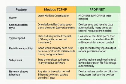
Firstly thank you for your valuable sharings.Could you compose a compherensive tutorial about Profibus and Profinet? Also if possible could you write a article about Siemens DCS(PCS7, SPPA T3000)? Thank you for yor