Inst ToolsInst ToolsInst Tools
  • Ask
  • Courses
  • Videos
  • Q & A
    • Interview
      • Instrumentation
      • Electronics
      • Electrical
      • Practical Questions
    • MCQ
      • Instrumentation MCQ
      • Electrical MCQ
      • Electronics MCQ
      • Control Systems MCQ
      • Analog Electronics MCQ
      • Digital Electronics MCQ
      • Power Electronics MCQ
      • Microprocessor MCQ
      • Multiple Choice Questions
  • EE
    • Electronics
      • Electronics Q & A
      • Electronic Basics
      • Electronic Devices & Circuits
      • Electronics Animation
      • Digital Electronics
    • Electrical
      • Electrical Basics
      • Electrical Q & A
      • Power Electronics
      • Electrical Machines
      • Electrical Animation
      • Power Systems
      • Switchgear & Protection
      • Transmission & Distribution
  • Measure
    • Control Valves
    • Calibration
    • Temperature
    • Pressure
    • Flow
    • Level
    • Analyzers
    • Switches
    • Vibration
    • Solenoid Valve
  • Control
    • PLC Tutorials
    • Control Systems
    • Safety Instrumented System (SIS)
    • Communication
    • Fire & Gas System
  • More
    • Design
    • Tools
    • Animation
    • Basics
    • Formulas
    • Standards
    • TextBooks
    • Common
    • Software
    • Excel Tools
    • Erection & Commissioning
    • Process Fundamentals
    • Videos
    • Books
Search
All rights reserved. Reproduction in whole or in part without written permission is prohibited.
Reading: How Much Pressure Indicated by Micromanometer?
Share
Notification Show More
Font ResizerAa
Inst ToolsInst Tools
Font ResizerAa
  • Courses
  • PLC Tutorials
  • Control Systems
Search
  • Ask
  • Courses
  • Videos
  • Q & A
    • Interview
    • MCQ
  • EE
    • Electronics
    • Electrical
  • Measure
    • Control Valves
    • Calibration
    • Temperature
    • Pressure
    • Flow
    • Level
    • Analyzers
    • Switches
    • Vibration
    • Solenoid Valve
  • Control
    • PLC Tutorials
    • Control Systems
    • Safety Instrumented System (SIS)
    • Communication
    • Fire & Gas System
  • More
    • Design
    • Tools
    • Animation
    • Basics
    • Formulas
    • Standards
    • TextBooks
    • Common
    • Software
    • Excel Tools
    • Erection & Commissioning
    • Process Fundamentals
    • Videos
    • Books
Follow US
All rights reserved. Reproduction in whole or in part without written permission is prohibited.
Inst Tools > Blog > Practical Questions > How Much Pressure Indicated by Micromanometer?

How Much Pressure Indicated by Micromanometer?

Last updated: June 2, 2020 1:34 pm
Editorial Staff
Practical Questions
No Comments
Share
3 Min Read
SHARE

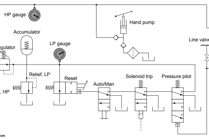
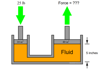
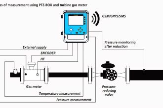
A simple way to make a micromanometer (an extremely sensitive manometer) is to connect two large-diameter vertical tubes by a small-diameter, transparent tube with an air bubble in it. The air bubble becomes the marker for reading pressure along a scale:

Contents
MicromanometerAnswer:Read Next:

Micromanometer

How Much Pressure indicated by Micromanometer

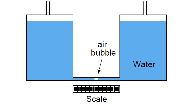
If both of the large vertical tubes are 2.5 inches in diameter, and the transparent, horizontal tube is 0.25 inches in diameter, how much differential pressure will be indicated by 1 inch of horizontal bubble displacement? Assume the use of water for the manometer liquid.

Answer:

1 inch of bubble motion represents 0.02 inches of water column pressure (differential), or 2/100 ”W.C., applied across this micromanometer.

To solve for this pressure, first determine the amount of liquid volume that would have to be displaced to move the bubble 1 inch. Since the bubble resides in a tube 0.25 inches in diameter, the volume for 1 inch of bubble motion is:

(1 inch)[π(0.25 inch / 2)2] = 0.04909 in3

This is a very small amount of liquid volume! The water levels in the larger (2.5 inch diameter) tubes will not have to change much to accommodate this tiny amount of displacement. Dividing the displaced fluid volume by the area of the vertical tubes will tell us how far the water levels must change in each of the vertical tubes:

(0.04909 in3) / [π(2.5 inch / 2)2] = 0.01 inch

So, a vertical liquid column height change of only 0.01 inch will cause a horizontal bubble displacement of 1 inch. Since there will be 0.01 inch of movement in each vertical tube, the combined total vertical displacement is twice this figure, or 0.02 inches of water column.

A much simpler way to solve this problem is to recognize that the vertical tube areas are 100 times as great as the horizontal tube (2.5 inches is ten times as large as 0.25 inches, and area is proportional to diameter squared), so 1 inch of horizontal fluid displacement is proportional to 1/100 inch of vertical fluid displacement.

Once again, since each vertical tube experiences 0.01 inch of vertical water level displacement, the total water column shift is 0.02 inches.

Read Next:

  • Level Objective Questions
  • Tube and tube fittings
  • Volumetric Flow Calculations
  • Inclined Water Manometer?
  • DP Transmitter Elevation

Credits: Tony R. Kuphaldt

Don't Miss Our Updates
Be the first to get exclusive content straight to your email.
We promise not to spam you. You can unsubscribe at any time.
Invalid email address
You've successfully subscribed !

Recommended Articles

Practical Level Sensors Questions and Answers
Pneumatic Moment-balance Differential Pressure Transmitter
Indentify Faults in Simple Lamp Circuit including Failed Wires
Calculate the Transmitter Values
A Question on Density Gauge
Practical Process Control System Questions & Answers – 7
Share This Article
Facebook Whatsapp Whatsapp LinkedIn Copy Link
Share
Leave a Comment

Leave a Reply Cancel reply

Your email address will not be published. Required fields are marked *

Stay Connected

128.3kFollowersLike
69.1kFollowersFollow
208kSubscribersSubscribe
38kFollowersFollow

Categories

Recent Comments

  • William Snyder on Top Non-PLC Certification Courses for Automation Professionals
  • Kamli on Top Free PLC Software
  • Guifty Shimica on Top Non-PLC Certification Courses for Automation Professionals
  • Guifty Shimica on Top Non-PLC Certification Courses for Automation Professionals

Related Articles

PLC Motor Control Circuit

Motor Trip Logic using PLC Programming

Hydraulic Actuated Lift

Oil and Air Pressure Actuated Lifts Questions

reactor vessel

Practical Process Control System Questions & Answers – 5

Level Transmitter trend

Identify Level Control Loop Tuning Problems

Resistance Temperature Detector (RTD) Questions

Resistance Temperature Detector (RTD) Questions – 1

Which instrument is faulty

Which Instrument is Faulty? Transmitter, Recorder, or Controller

Questions on Resistive Tape Level Sensor

Questions on Resistive Tape Level Sensor

PLC Program three-phase electric motor

Identify the Problem in the PLC Program

More Articles

Open Tank Interface Level measurement principle

Open Tank Interface Level Measurement

4-wire RTD Bridge Circuit

Why we use Wheatstone bridge in RTD?

Oil in Water Analyzer Principle

Oil in Water Analyzer Working Principle

Solenoid Valve Terminology

How a Solenoid valve works

Voting System in PLC

Voting Concept in Package Safety System

Control Valve in Nutshell - Valve Design and Selection Factors

Control Valve in Nutshell – Valve Design and Selection Factors

Modern Instrumentation & IoT: Key Innovations & Trends

Modern Instrumentation & IoT: Key Innovations & Trends

Interview Questions on Control Valves

Interview Questions on Control Valves

Follow US
All rights reserved. Reproduction in whole or in part without written permission is prohibited.
Welcome Back!

Sign in to your account

Username or Email Address
Password

Lost your password?