Inst ToolsInst ToolsInst Tools
  • Courses
  • Automation
    • PLC
    • Control System
    • Safety System
    • Communication
    • Fire & Gas System
  • Instrumentation
    • Design
    • Pressure
    • Temperature
    • Flow
    • Level
    • Vibration
    • Analyzer
    • Control Valve
    • Switch
    • Calibration
    • Erection & Commissioning
  • Interview
    • Instrumentation
    • Electrical
    • Electronics
    • Practical
  • Q&A
    • Instrumentation
    • Control System
    • Electrical
    • Electronics
    • Analog Electronics
    • Digital Electronics
    • Power Electronics
    • Microprocessor
  • Request
Search
  • Books
  • Software
  • Projects
  • Process
  • Tools
  • Basics
  • Formula
  • Power Plant
  • Root Cause Analysis
  • Electrical Basics
  • Animation
  • Standards
  • 4-20 mA Course
  • Siemens PLC Course
Reading: Pressure Gauge with Block and Bleed Valves
Share
Font ResizerAa
Inst ToolsInst Tools
Font ResizerAa
  • Courses
  • Design
  • PLC
  • Interview
  • Control System
Search
  • Courses
  • Automation
    • PLC
    • Control System
    • Safety System
    • Communication
    • Fire & Gas System
  • Instrumentation
    • Design
    • Pressure
    • Temperature
    • Flow
    • Level
    • Vibration
    • Analyzer
    • Control Valve
    • Switch
    • Calibration
    • Erection & Commissioning
  • Interview
    • Instrumentation
    • Electrical
    • Electronics
    • Practical
  • Q&A
    • Instrumentation
    • Control System
    • Electrical
    • Electronics
    • Analog Electronics
    • Digital Electronics
    • Power Electronics
    • Microprocessor
  • Request
Follow US
All rights reserved. Reproduction in whole or in part without written permission is prohibited.
Inst Tools > Blog > Pressure Measurement > Pressure Gauge with Block and Bleed Valves

Pressure Gauge with Block and Bleed Valves

Last updated: October 1, 2020 5:27 pm
Editorial Staff
Pressure Measurement Practical Questions
No Comments
Share
4 Min Read
SHARE

In connecting a pressure transmitter or other pressure-measuring instrument to a process pipe or vessel, there must be some means of “disconnecting” the instrument from the pressurized process so that it may be calibrated or removed safely without depressurizing the entire process.

Usually, this feature is provided in the form of an instrument “manifold,” consisting of one or more valves between the instrument and the process pipe or vessel.

Pressure Gauge with Block and Bleed Valves

Take this pressure gauge installation, for example:

Pressure Gauge with Block and Bleed Valves

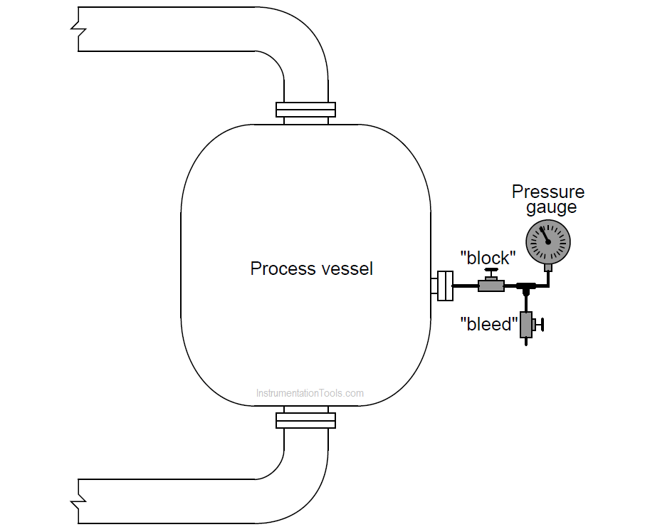
Two small valves connect the process vessel to the pressure gauge through a tee fitting, one called the “block” and the other called the “bleed.” In normal operation, the “block” valve remains in the open position and the “bleed” valve remains in the closed position.

Suppose you wished to remove this pressure gauge from the process vessel and take it to the instrument shop for re-calibration. In what sequence would you operate the “block” and “bleed” valves before loosening the gauge from the tubing?

After the gauge had been calibrated and installed, and you are ready to place it back in service, how would you sequence the opening and closing of the “block” and “bleed” valves? Be very careful about the sequence of your steps!

Answer:

Removing the gauge from service:

  • Close the “block” valve.
  • Open the “bleed” valve. If the process fluid is dangerous (toxic, flammable, etc.), be very careful when “bleeding” it to the atmosphere!
  • Place lock-out tags on both valve handles to notify operators and technicians of the instrument’s removal and pending return.
  • Remove the gauge from the piping or tubing.

It is very important to place tags on the valve handles as notifiers of your service to the gauge. Even if these tags do not serve a safety purpose (i.e. it is visually obvious that the “block” valve should not be opened when there is no instrument connected to it), they still notify anyone looking for the missing gauge that you are servicing it and will have it returned by a certain time/date.

Placing the gauge back into service:

  • Re-attach the gauge to the piping or tubing.
  • Remove the lock-out tags on both valve handles.
  • Close the “bleed” valve.
  • Open the “block” valve.

An added touch of professionalism when opening the “block” valve is to not leave it open all the way so that the handle cannot turn any further counterclockwise. Instead, open it all the way (counterclockwise) until you feel the handle “stop,” then turn it back clockwise (in the closing direction) about 1/4 turn.

This helps to prevent the valve from seizing in the fully open position, by backing the valve stem off the reverse seat. Valves left to sit in the fully open position have a tendency to become “frozen” in that position. The worse thing about a “frozen” valve is that you cannot determine what position it is in by feel!

Share your answers with us through the below comments section.

Read Next:

  • Pressure Transmitter Manifolds
  • Instrumentation and Control MCQ
  • Pressure Gauge Datasheet
  • Temperature Controller Problem
  • Pressure Measurement MCQ

Credits: Tony R. Kuphaldt

Don't Miss Our Updates
Be the first to get exclusive content straight to your email.
We promise not to spam you. You can unsubscribe at any time.
Invalid email address
You've successfully subscribed !

Continue Reading

Analytical Control System of Heat Exchanger Questions
Calculate the Voltage across Voltmeters of Thermocouple
Pressure Transmitter Calibration Procedure
Simulate Different Values for Pressure Instrument Under Test
Simple Pressure Repeater
Type E thermocouple Calculations
Share This Article
Facebook Whatsapp Whatsapp LinkedIn Copy Link
Share
Leave a Comment

Leave a Reply Cancel reply

Your email address will not be published. Required fields are marked *

Stay Connected

128.3kFollowersLike
69.1kFollowersFollow
210kSubscribersSubscribe
38kFollowersFollow

Categories

Explore More

Inductance Type Pressure Transducers Principle
Types of Pressure Measuring Scales
Float-type Level Switch for Sensing Low Oil Level
LRV and URV of PT for Extreme Limits of Empty and Full
Calculate Process Temperature using a Thermocouple
Two-Liquid Manometer Principle
Top 30 Interview Questions on Pressure Measuring Devices
Practical Process Control System Questions & Answers – 9

Keep Learning

Practical Control Systems Questions & Answers - 2

Practical Process Control System Questions & Answers – 2

U-tube Manometer unEqual Limb Type

U-tube Manometer with equal & unequal limb types

Impulse Line Problems

What are Impulse Lines? – Impulse Line Problems & Solutions

Pressure Gauge Selection

Pressure Gauge Selection

Uncertainty Calculations of Pressure Calibration

Uncertainty Calculations of Pressure Calibration

Siemens S7-200 PLC Ladder Logic

Programmable Logic Controller (PLC) Questions and Answers – 10

PLC program to control pump

Troubleshooting PLC Permissive Inputs

C-Bourdon Tube

C-Bourdon Tube Pressure Gauge Theory

Learn More

Garage Door Roller Shutter

Shutter Door Control using Motor and Limit Switches

reverse-biased varactor diode

Varactor Diode Operation

SCADA Systems

SCADA Systems

Square root extractor Parts

What is a Square Root Extractor? – DP Flow Measurement

Electronic Devices & Circuits Objective Questions

Electronic Devices & Circuits Quiz – Set 13

Float Operated Level Switches

Float Level Switch Working Principle

Thermowell-Insertion-and-Immersion-Length

What is a Transformer Tap Changer

PLC Programming Example on Timers Function Block

PLC Programming Example on Timers Function Block

Menu

  • About
  • Privacy Policy
  • Copyright

Quick Links

  • Learn PLC
  • Helping Hand
  • Part Time Job

YouTube Subscribe

Follow US
All rights reserved. Reproduction in whole or in part without written permission is prohibited.
Welcome Back!

Sign in to your account

Username or Email Address
Password

Lost your password?