Inst ToolsInst ToolsInst Tools
  • Courses
  • Videos
  • Q & A
    • Interview
      • Instrumentation
      • Electronics
      • Electrical
      • Practical Questions
    • MCQ
      • Instrumentation MCQ
      • Electrical MCQ
      • Electronics MCQ
      • Control Systems MCQ
      • Analog Electronics MCQ
      • Digital Electronics MCQ
      • Power Electronics MCQ
      • Microprocessor MCQ
      • Multiple Choice Questions
  • EE
    • Electronics
      • Electronics Q & A
      • Electronic Basics
      • Electronic Devices & Circuits
      • Electronics Animation
      • Digital Electronics
    • Electrical
      • Electrical Basics
      • Electrical Q & A
      • Power Electronics
      • Electrical Machines
      • Electrical Animation
      • Power Systems
      • Switchgear & Protection
      • Transmission & Distribution
  • Measure
    • Control Valves
    • Calibration
    • Temperature
    • Pressure
    • Flow
    • Level
    • Analyzers
    • Switches
    • Vibration
    • Solenoid Valve
  • Control
    • PLC Tutorials
    • Control Systems
    • Safety Instrumented System (SIS)
    • Communication
    • Fire & Gas System
  • More
    • Design
    • Tools
    • Animation
    • Basics
    • Formulas
    • Standards
    • TextBooks
    • Common
    • Software
    • Excel Tools
    • Erection & Commissioning
    • Process Fundamentals
    • Videos
    • Books
Search
All rights reserved. Reproduction in whole or in part without written permission is prohibited.
Reading: Pressure Gauge Pulsation Damping
Share
Notification Show More
Font ResizerAa
Inst ToolsInst Tools
Font ResizerAa
  • Courses
  • PLC Tutorials
  • Control Systems
Search
  • Courses
  • Videos
  • Q & A
    • Interview
    • MCQ
  • EE
    • Electronics
    • Electrical
  • Measure
    • Control Valves
    • Calibration
    • Temperature
    • Pressure
    • Flow
    • Level
    • Analyzers
    • Switches
    • Vibration
    • Solenoid Valve
  • Control
    • PLC Tutorials
    • Control Systems
    • Safety Instrumented System (SIS)
    • Communication
    • Fire & Gas System
  • More
    • Design
    • Tools
    • Animation
    • Basics
    • Formulas
    • Standards
    • TextBooks
    • Common
    • Software
    • Excel Tools
    • Erection & Commissioning
    • Process Fundamentals
    • Videos
    • Books
Follow US
All rights reserved. Reproduction in whole or in part without written permission is prohibited.
Inst Tools > Blog > Pressure Measurement > Pressure Gauge Pulsation Damping

Pressure Gauge Pulsation Damping

Last updated: November 1, 2018 9:37 am
Editorial Staff
Pressure Measurement
No Comments
Share
5 Min Read
SHARE

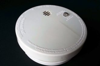
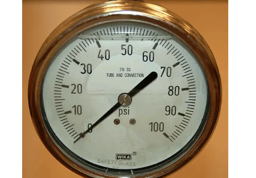
A simple way to mitigate the effects of pulsation on a pressure gauge is to fill the inside of the gauge with a viscous liquid such as glycerin or oil. The inherent friction of this fill liquid has a “shock absorber” quality which damps the gauge mechanism’s oscillatory motion and helps protect against damage from pulsations or from external vibration. This method is ineffectual for high-amplitude pulsations, though. An oil-filled pressure gauge may be seen in the following photograph. Note the air bubble near the top of the gauge face, which is the only visual indication of an oil filling:

Pressure Gauge pulsation damping

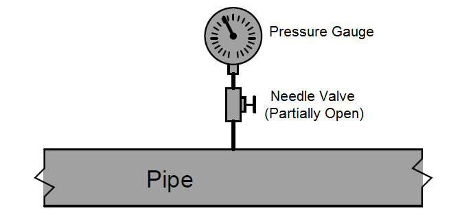
A more sophisticated method for damping pulsations seen by a pressure instrument is called a snubber, and it consists of a fluid restriction placed between with the pressure sensor and the process. The simplest example of a snubber is a simple needle valve (an adjustable valve designed for low flow rates) placed in a mid-open position, restricting fluid flow in and out of a pressure gauge:

Pressure Gauge with Needle Valve

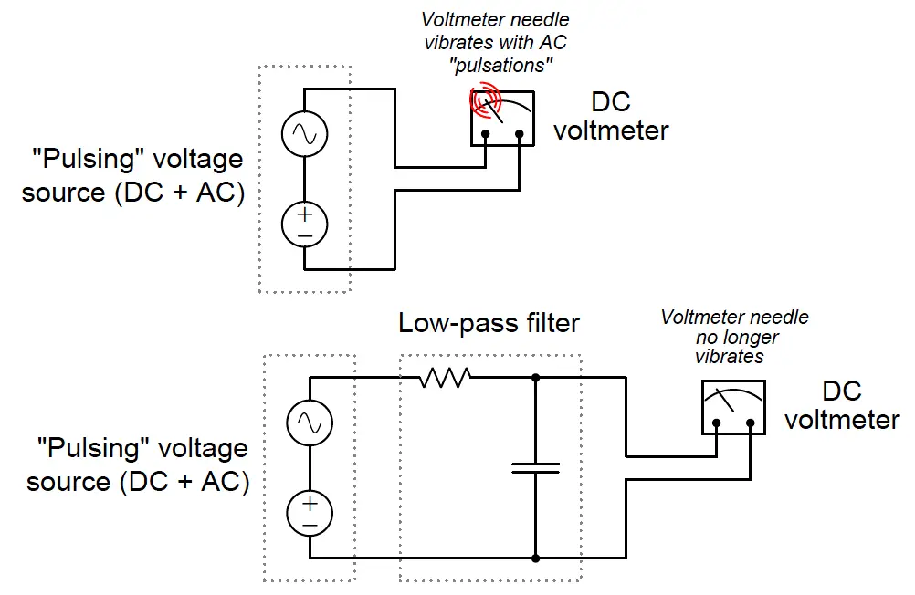
At first, the placement of a throttling valve between the process and a pressure-measuring instrument seems rather strange, because there should not be any continuous flow in or out of the gauge for such a valve to throttle! However, a pulsing pressure causes a small amount of alternating flow in and out of the pressure instrument, owing to the expansion and contraction of the mechanical pressure-sensing element (bellows, diaphragm, or bourdon tube). The needle valve provides a restriction for this flow which, when combined with the fluid capacitance of the pressure instrument, combine to form a low-pass filter of sorts. By impeding the flow of fluid in and out of the pressure instrument, that instrument is prevented from “seeing” the high and low peaks of the pulsating pressure. Instead, the instrument registers a much steadier pressure over time. An electrical analogy for a pressure snubber is an RC low-pass filter circuit “damping” voltage pulsations from reaching a DC voltmeter:

Pressure Gauge pulsation

One potential problem with the needle valve solution is that the small orifice inside the needle valve may plug up over time with debris from dirty process fluid. This, of course, would be bad because plugging will cause the pressure instrument to respond too slowly, or not at all if the plugging is complete.

A solution to this problem is to fill the pressure sensor mechanism with a clean liquid (called a fill fluid) and use that fill fluid to transfer pressure from the process fluid to the pressure-sensing element using a slack diaphragm or some other membrane separating the process fluid from the fill fluid:

Pressure Gauge with Isolating diaphragm

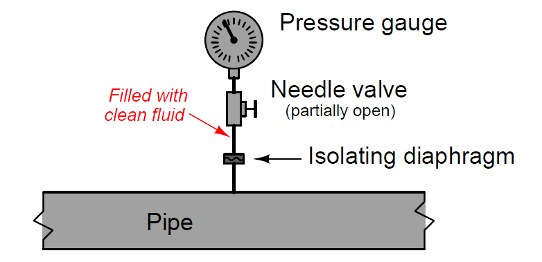
It should be noted that most pressure snubbers utilize a fixed-geometry orifice rather than an adjustable needle valve to dampen pressure pulsations seen at the pressure gauge. In order for the fill fluid and isolating diaphragm to work effectively, there cannot be any gas bubbles in the fill fluid – it must be a “solid” hydraulic system from the diaphragm to the sensing element. Gas bubbles present in the filled system would make that volume compressible, which means the isolating diaphragm would have to move more than necessary to transfer pressure to the instrument’s sensing element. This would mean motion at the isolating diaphragm caused by process pressure changes would be “lost” and not fully transferred to the instrument’s sensing element, thereby introducing a pressure measurement error. For this reason, isolating diaphragm systems for pressure instruments are usually “packed” with fill fluid at the point and time of manufacture, then sealed in such a way that they cannot be opened for any form of maintenance. Consequently, any fill fluid leak in such a system immediately ruins it.

 Credits : Tony R. Kuphaldt – Creative Commons Attribution 4.0 License

Don't Miss Our Updates
Be the first to get exclusive content straight to your email.
We promise not to spam you. You can unsubscribe at any time.
Invalid email address
You've successfully subscribed !

Recommended Articles

Pressure Transmitters Purged impulse lines
Types of Bourdon Tube
Commissioning a Differential Pressure Transmitter in a Pressurized Boiler Steam Drum
Pressure Gauges with Diaphragm Sensor Principle
Information on the Pressure Gauge Dial
How Capacitive Pressure Sensor Works ?
Share This Article
Facebook Whatsapp Whatsapp LinkedIn Copy Link
Share
Leave a Comment

Leave a Reply Cancel reply

Your email address will not be published. Required fields are marked *

Stay Connected

128.3kFollowersLike
69.1kFollowersFollow
208kSubscribersSubscribe
38kFollowersFollow

Categories

Recent Comments

  • William Snyder on Top Non-PLC Certification Courses for Automation Professionals
  • Kamli on Top Free PLC Software
  • Guifty Shimica on Top Non-PLC Certification Courses for Automation Professionals
  • Guifty Shimica on Top Non-PLC Certification Courses for Automation Professionals

Related Articles

5 Valve manifold

5 Valve Manifold Operation

Differential Pressure Gauge Principle

Differential Pressure Gauge Principle

Inclined-limb Manometer Formula - 2

Inclined-limb Manometer Principle

Absolute Pressure Gauges Principle

Absolute Pressure Gauges Principle

Pressure gauges with capsule elements

Pressure Gauges with Capsule Sensor Principle

pressure gauge snubber

Pressure Gauge Snubbers

Measuring process vessel clogging

DP Transmitter Applications

Pressure Gauge Parts

Pressure Gauges with Bourdon Tube Principle

More Articles

Calculate Total Hydrostatic Pressure at Bottom of Vessel

Calculate Total Hydrostatic Pressure at Bottom of Vessel

PLC Program for Automatic Heating and Mixing of Products

Heating and Mixing of Products using PLC Example Tutorial

Applications of Photo diodes

Applications of Photo diodes

Pressure Gauges Common Problems

Pressure Gauges : Common Causes for Failures and Their Effective Solutions

Infrared Open Path Gas Detectors Operation

Infrared Open Path Gas Detectors Working Principle

Opposite Acting Control Valves Application

PLC Ladder Logic for Opposite Acting Control Valves Application

Digital Electronics Multiple Choice Questions

4-Bit Parallel Adder and Subtractor Objective Questions

Electrical Machines Questions and Answers

DC Generators Rotating Amplifiers Quiz

Follow US
All rights reserved. Reproduction in whole or in part without written permission is prohibited.
Welcome Back!

Sign in to your account

Username or Email Address
Password

Lost your password?