Inst ToolsInst ToolsInst Tools
  • Courses
  • Automation
    • PLC
    • Control System
    • Safety System
    • Communication
    • Fire & Gas System
  • Instrumentation
    • Design
    • Pressure
    • Temperature
    • Flow
    • Level
    • Vibration
    • Analyzer
    • Control Valve
    • Switch
    • Calibration
    • Erection & Commissioning
  • Interview
    • Instrumentation
    • Electrical
    • Electronics
    • Practical
  • Q&A
    • Instrumentation
    • Control System
    • Electrical
    • Electronics
    • Analog Electronics
    • Digital Electronics
    • Power Electronics
    • Microprocessor
  • Request
Search
  • Books
  • Software
  • Projects
  • Process
  • Tools
  • Basics
  • Formula
  • Power Plant
  • Root Cause Analysis
  • Electrical Basics
  • Animation
  • Standards
  • 4-20 mA Course
  • Siemens PLC Course
Reading: Pressure to Current (P/I) Converter Principle
Share
Font ResizerAa
Inst ToolsInst Tools
Font ResizerAa
  • Courses
  • Design
  • PLC
  • Interview
  • Control System
Search
  • Courses
  • Automation
    • PLC
    • Control System
    • Safety System
    • Communication
    • Fire & Gas System
  • Instrumentation
    • Design
    • Pressure
    • Temperature
    • Flow
    • Level
    • Vibration
    • Analyzer
    • Control Valve
    • Switch
    • Calibration
    • Erection & Commissioning
  • Interview
    • Instrumentation
    • Electrical
    • Electronics
    • Practical
  • Q&A
    • Instrumentation
    • Control System
    • Electrical
    • Electronics
    • Analog Electronics
    • Digital Electronics
    • Power Electronics
    • Microprocessor
  • Request
Follow US
All rights reserved. Reproduction in whole or in part without written permission is prohibited.
Inst Tools > Blog > Control Valves > Pressure to Current (P/I) Converter Principle

Pressure to Current (P/I) Converter Principle

Last updated: August 26, 2019 3:07 pm
Editorial Staff
Control Valves
5 Comments
Share
2 Min Read
SHARE

We can construct a pressure to current converter using a Flapper- Nozzle arrangement , Bellows and a Linear Variable Differential Transformer (LVDT) circuit.

Input pressure is given to Flapper-Nozzle arrangement and the output current will come through the LVDT.

Also Read : What is Flapper/Nozzle ?

Flapper Nozzle arrangement: It is type of pressure controlling device. It controls the input pressure by the moving the Flapper away or towards the nozzle, if we need high pressure, then nozzle will be closed by the Flapper and if we need less pressure, then nozzle will be opened by moving flapper away.

Bellows:- Bellows are one type of pressure measuring devices. They are the elements which will expand as per the applied pressure. Based on the displacement we can measure the pressure.

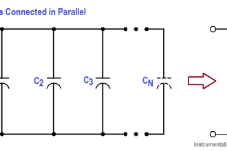
Linear Variable Differential Transformer (LVDT): It works on the principle of Mutual Inductance. In the LVDT three coils will be present. Primary coil is connected to a power source and secondary coils are connected in series opposition method.

At initial position, the voltage induced will be zero. If the core displaces, then due to inductance, voltage will be induced into the coils, resulting in the current.

Pressure to Current Converter

Pressure to Current Converter

First Input pressure is supplied to the Flapper- Nozzle arrangement.  Then it will supplied through a pipe and that pressure is given as input to the bellows. These bellows are connected to the Core of LVDT.

When pressure is applied to bellows, they will expand thus core displaces and the voltage is induced on the secondary coils of LVDT.

As voltage is induced, current will flow through the coil. That current is proportional to the input pressure applied. Thus Pressure is converted into equivalent current.

When compared with standard values we can covert 3-15 P.S.I of pressure can be converted to 4-20 mA of current

Articles You May Like :

Pressure Regulator Flapper-Nozzle

Transformer Theory of Operation

Pneumatic Sensing Elements

Electronic Pressure Sensors

C-Bourdon Tube Pressure Gauge

Don't Miss Our Updates
Be the first to get exclusive content straight to your email.
We promise not to spam you. You can unsubscribe at any time.
Invalid email address
You've successfully subscribed !

Continue Reading

Butterfly Valves – Concentric, Double-offset, and Triple-offset
Pneumatic Control Valve Actuators
Control Valve Cv calculation
Valve Materials Comparison Notes
Why we Require Dual SOV on a Control Valve?
Root Cause Analysis for Tank Overflow due to Valve Problem
Share This Article
Facebook Whatsapp Whatsapp LinkedIn Copy Link
Share
5 Comments
  • Pravin Maheshkar says:
    April 29, 2017 at 7:07 am

    nice illustration through clear picture…

    Reply
  • Manikandan says:
    July 7, 2017 at 4:09 am

    This explanation shows your experience…

    Reply
  • Sai kiran says:
    February 9, 2019 at 10:28 am

    What happens if there is no flapper and pivot…

    Reply
  • Raed says:
    July 4, 2019 at 7:15 pm

    Many thanks

    Reply
  • Shahan Ahmed says:
    August 26, 2019 at 4:06 pm

    It’s a helpful site

    Reply

Leave a Reply Cancel reply

Your email address will not be published. Required fields are marked *

Stay Connected

128.3kFollowersLike
69.1kFollowersFollow
210kSubscribersSubscribe
38kFollowersFollow

Categories

Explore More

Functional Testing of Control Valve Positioners
What is a Servo Valve? – Principle and Advantages
Face to Face Dimension of Control Valve
What is Valve Packing ?
Self Actuated Pressure Control Valve Principle
Difference Between the Control Valve and Shut-off Valve
What is Flapper Nozzle System ?
Complementary Control Valve Sequence

Keep Learning

Pinch Valve

What is Pinch Valve ?

four-way-solenoid-valve-diagram

Four Way Solenoid Valve Working Principle

Valves MCQ

Valves MCQ

ON OFF Valve Parts

ON OFF Valve Preventive Maintenance and Testing Procedure

Valve stem travel

Control Valves Mechanical Friction Problems

Interview Questions on Control Valves

Interview Questions on Control Valves

gate-valve-principle-animation

Basics of Gate Valves

Air Lock Relay Working Principle

Control Valve Air Lock Relay Working Principle

Learn More

Pressure Manometer

Types of Manometers

Smart Valve Monitoring

SIS Instruments and Valves Inline Testing – Safety Instrumented System

Electrical Engineering Materials Objective Questions

200 Electrical Engineering Materials Objective Questions & Answers

pH Monitoring System Triggers an Alarm

pH Monitoring System Triggers an Alarm

PLC Ladder Logic for Motor Control

PLC Program for Motor Starter

Sorting and Counting Products on Conveyors by Color

PLC Programming for Multi-Color Sorting Conveyor System

Advanced Microcontroller Projects Using Proteus Simulation

Advanced Microcontroller Projects Using Proteus Simulation

Strain Gauge Animation

Menu

  • About
  • Privacy Policy
  • Copyright

Quick Links

  • Learn PLC
  • Helping Hand
  • Part Time Job

YouTube Subscribe

Follow US
All rights reserved. Reproduction in whole or in part without written permission is prohibited.
Welcome Back!

Sign in to your account

Username or Email Address
Password

Lost your password?