Inst ToolsInst ToolsInst Tools
  • Courses
  • Automation
    • PLC
    • Control System
    • Safety System
    • Communication
    • Fire & Gas System
  • Instrumentation
    • Design
    • Pressure
    • Temperature
    • Flow
    • Level
    • Vibration
    • Analyzer
    • Control Valve
    • Switch
    • Calibration
    • Erection & Commissioning
  • Interview
    • Instrumentation
    • Electrical
    • Electronics
    • Practical
  • Q&A
    • Instrumentation
    • Control System
    • Electrical
    • Electronics
    • Analog Electronics
    • Digital Electronics
    • Power Electronics
    • Microprocessor
  • Request
Search
  • Books
  • Software
  • Projects
  • Process
  • Tools
  • Basics
  • Formula
  • Power Plant
  • Root Cause Analysis
  • Electrical Basics
  • Animation
  • Standards
  • 4-20 mA Course
  • Siemens PLC Course
Reading: PLC Programming for 3 Motors control in Ladder logic
Share
Notification Show More
Font ResizerAa
Inst ToolsInst Tools
Font ResizerAa
  • Courses
  • Design
  • PLC
  • Interview
  • Control System
Search
  • Courses
  • Automation
    • PLC
    • Control System
    • Safety System
    • Communication
    • Fire & Gas System
  • Instrumentation
    • Design
    • Pressure
    • Temperature
    • Flow
    • Level
    • Vibration
    • Analyzer
    • Control Valve
    • Switch
    • Calibration
    • Erection & Commissioning
  • Interview
    • Instrumentation
    • Electrical
    • Electronics
    • Practical
  • Q&A
    • Instrumentation
    • Control System
    • Electrical
    • Electronics
    • Analog Electronics
    • Digital Electronics
    • Power Electronics
    • Microprocessor
  • Request
Follow US
All rights reserved. Reproduction in whole or in part without written permission is prohibited.
Inst Tools > Blog > PLC Tutorials > PLC Programming for 3 Motors control in Ladder logic

PLC Programming for 3 Motors control in Ladder logic

Last updated: March 4, 2021 2:38 pm
Editorial Staff
PLC Tutorials
3 Comments
Share
2 Min Read
SHARE

Write the PLC Programming Motors logic for the following problem.

Contents
PLC Programming MotorsProgram Description:Program Output:When M1 turns ON,When M1 & M2 turns ONWhen the Third motor Turns ON,Conclusion:
  1. There are three motors (M1, M2 & M3), having a separate start and stop push button.
  2. M1 must be running before starting of M2 and M3 motor.
  3. M2 and M3 can start and stop without affecting M1 operation.
  4. Only two motors can run at the time. Starting of the third motor will shut down all the outputs immediately irrespective of its input.

PLC Programming Motors

PLC Programming for 3 Motors control in Ladder logic
PLC Programming Motors control
Example PLC Program for Motor

Program Description:

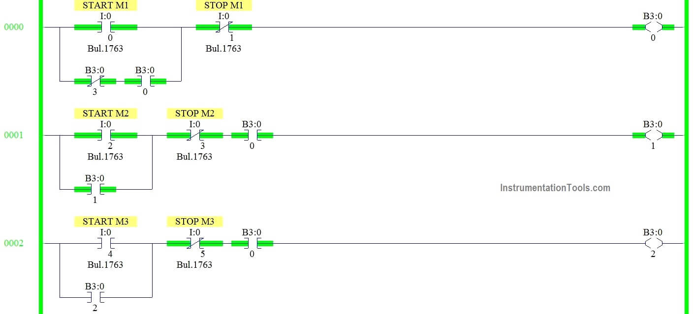
Rung 0000:

Start/Stop PB latched with memory B3:0/0 for Motor 1.B3:0/3 is connected in series with latch memory to turn off all motors.

Rung 0001:

Start/Stop PB latched with memory B3:0/1 for Motor 2 .B3:0/0 is connected in series to turn on M2 only after M1.

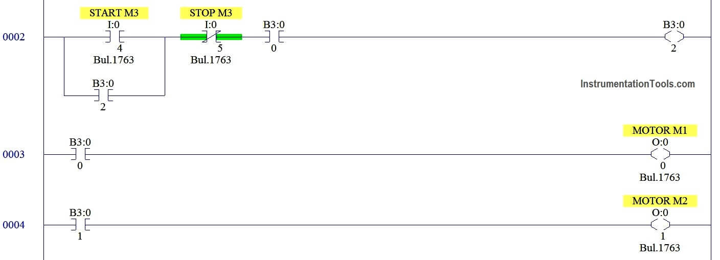
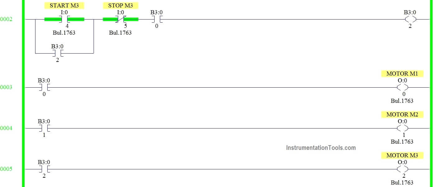
Rung 0002:

Start/Stop PB latched with memory B3:0/2 for Motor 3 .B3:0/0 is connected in series to turn on M3 only after M1.

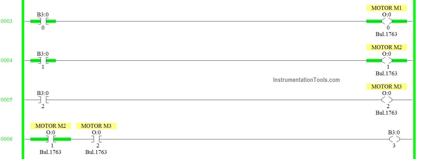
Rung 0003:

Turning on M1 when B3:0/0 turns ON

Rung 0004:

Turning on M2 when B3:0/1 turns ON

Rung 0005:

Turning on M3 when B3:0/2 turns ON

Rung 0006:

M2 and M3 outputs are connected in series to enable B3:0/3

Program Output:

When M1 turns ON,
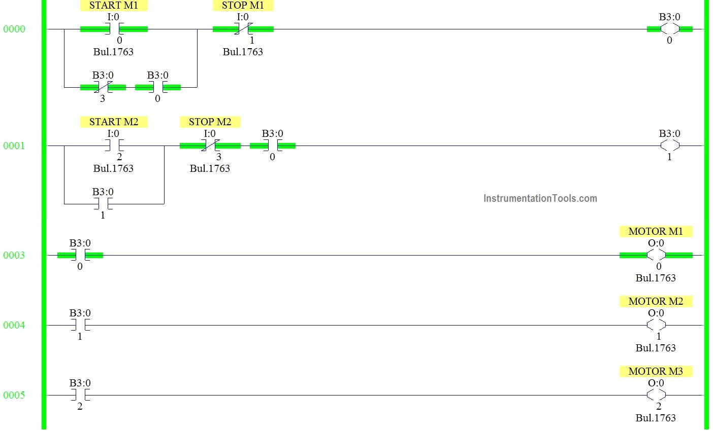
PLC Motor Control Circuit Example

When M1 & M2 turns ON

Ladder Logic for Motor Control
Basic Motors Control using Ladder Logic

When the Third motor Turns ON,

Motor Ladder Diagrams

Conclusion:

We can use this example to understand the programming logic in Allen Bradley PLC.

Author: Hema Sundaresan

If you liked this article, then please subscribe to our YouTube Channel for PLC and SCADA video tutorials.

You can also follow us on Facebook and Twitter to receive daily updates.

Read Next:
OFF Delay Timer in PLC

PLC Motor Permissive

ON OFF Control using PLC

PLC Programming Example

PLC Simulate Gate Array Logic

Don't Miss Our Updates
Be the first to get exclusive content straight to your email.
We promise not to spam you. You can unsubscribe at any time.
Invalid email address
You've successfully subscribed !

Continue Reading

PID with Practical Example
D Flip Flop PLC Ladder Logic
PLC Interlock Logic with First Input Priority
Difference between Signal Cables and Control Cables
Using Clock Memory Bits in TIA Portal – Siemens PLC
What is Loop Checking?
Share This Article
Facebook Whatsapp Whatsapp LinkedIn Copy Link
Share
3 Comments
  • Himangshu kumar Biswas says:
    January 14, 2020 at 2:10 pm

    Thanks.

    Reply
  • REGGIE AKUTA says:
    February 4, 2024 at 7:56 am

    I know it’s been four years since this post of 3 motors. It seems that your third motor is not turning all out puts off.

    Reply
  • Leo says:
    July 18, 2024 at 9:41 am

    Write the plc logic for the following conditions
    There are three motor m1 m2 m3 having a separate Start and stop push button
    m1 must be running before starting of m2 m3 motor
    Only one motor run at time

    Reply

Leave a Reply Cancel reply

Your email address will not be published. Required fields are marked *

Stay Connected

128.3kFollowersLike
69.1kFollowersFollow
210kSubscribersSubscribe
38kFollowersFollow

Categories

Explore More

Free InTouch SCADA Tutorial Course for Beginners
PLC Connection between Instrument, Junction Box, Marshalling & System Cabinet
PLC SCADA Engineers Interview Questions and Answers
PLC Program for Latching and unlatching Circuit
Siemens PLC Interview Questions and Answers
Basic Conveyor System for Product Handling in Omron PLC
Learn about SCADA and HMI Systems
Understanding the Scan Cycle of SIEMENS PLC

Keep Learning

DCS Marshalling Cabinet

The Purpose of Marshalling Cabinet or Marshalling Panel

Siemens PLC

Will PLCs become obsolete?

PLC analog output card

PLC Analog I/O and Network I/O

How to Safely Design Automation System for Hazardous Environments?

Automation System for Hazardous Environments

LED Indications on PLC

Getting to Know the LED Indications on GE Make PLC

Siemens Simatic HMI

How to Design an Effective HMI? – Human Machine Interface

Automated Test Bench - Complex PLC Programming Examples

Automated Test Bench – Complex PLC Programming Examples

How-to do Security of SCADA Systems

How-to do Security of SCADA Systems?

Learn More

Differential Pressure Sensor for Filtration Monitoring

Differential Pressure Sensor for Filtration Monitoring

Omron PLC for Product Painting with Integrated Weighing System

Omron PLC for Product Painting with Integrated Weighing System

LRV and URV of PT for Extreme Limits of Empty and Full

LRV and URV of PT for Extreme Limits of Empty and Full

Tags in Functional Block Diagram in Studio 5000

Sheets, Tags, Elements in Functional Block Diagram of Studio 5000

Grounding Electronic Equipment

Importance of Grounding Electronic Equipment

Top 100 PLC Projects List

Top 100 PLC Projects List

Direct Acting Solenoid Valve

Top 5 Things for selecting a Solenoid Valve

Power Electronics Objective Questions

Power Electronics Objective Questions

Menu

  • About
  • Privacy Policy
  • Copyright

Quick Links

  • Learn PLC
  • Helping Hand
  • Part Time Job

YouTube Subscribe

Follow US
All rights reserved. Reproduction in whole or in part without written permission is prohibited.
Welcome Back!

Sign in to your account

Username or Email Address
Password

Lost your password?